Service Manuals, User Guides, Schematic Diagrams or docs for : . Car Manuals Dodge Neon 1997.1999.2000.2004 Approved Dodge Neon 1999 epl_21
<< Back | HomeMost service manuals and schematics are PDF files, so You will need Adobre Acrobat Reader to view : Acrobat Download Some of the files are DjVu format. Readers and resources available here : DjVu Resources
For the compressed files, most common are zip and rar. Please, extract files with Your favorite compression software ( WinZip, WinRAR ... ) before viewing. If a document has multiple parts, You should download all, before extracting.
Good luck. Repair on Your own risk. Make sure You know what You are doing.
Image preview - the first page of the document

>> Download epl_21 documenatation <<
Text preview - extract from the document
PL                                                                                                     TRANSAXLE        21 - 1


                                                     TRANSAXLE
                                                          CONTENTS

                                                            page                                                         page

DESCRIPTION AND OPERATION                                            REMOVAL AND INSTALLATION
  BRAKE TRANSMISSION SHIFT INTERLOCK                                  BRAKE TRANSMISSION SHIFT INTERLOCK
   (BTSI) SYSTEM . . . . . . . . . . . . . . . . . . . . . . . . 1      (BTSI) CABLE ASSEMBLY . . . . . . . . . . . . . . . . 2
DIAGNOSIS AND TESTING                                                ADJUSTMENTS
  BRAKE TRANSMISSION SHIFT INTERLOCK                                  BRAKE TRANSMISSION SHIFT INTERLOCK
   (BTSI) SYSTEM . . . . . . . . . . . . . . . . . . . . . . . . 1      (BTSI) SYSTEM ADJUSTMENT . . . . . . . . . . . . 4

DESCRIPTION AND OPERATION
BRAKE TRANSMISSION SHIFT INTERLOCK
(BTSI) SYSTEM
   The Brake Transmission Shift Interlock (BTSI)
System, is a cable and solenoid operated system. It
interconnects the automatic transmission floor
mounted shifter to the steering column ignition
switch. The BTSI system locks the shifter into the
PARK position. The BTSI system is engaged when-
ever the ignition switch is in the LOCK or ACCES-
SORY position.
   An additional electrically activated feature will
prevent shifting out of the PARK position unless the
brake pedal is depressed at least one-half an inch. A
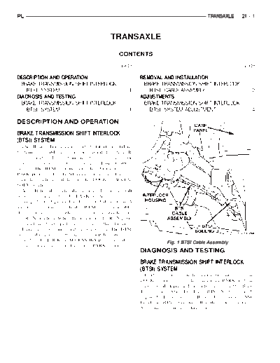
solenoid integrated with the BTSI cable assembly
(Fig. 1) is energized when the ignition switch is in
the RUN position. When the key is in the RUN posi-
tion and the brake pedal is depressed, the shifter is
unlocked and will move into any position. The BTSI
system also prevents the ignition switch from being
turned to the LOCK or ACCESSORY position, unless
                                                                                  Fig. 1 BTSI Cable Assembly
the shifter is fully locked into the PARK position.
                                                                     DIAGNOSIS AND TESTING
                                                                     BRAKE TRANSMISSION SHIFT INTERLOCK
                                                                     (BTSI) SYSTEM
                                                                       If the ignition switch cannot be turned to the
                                                                     LOCK position, with the shifter in PARK and the
                                                                     brake pedal depressed, an adjustment of the Brake
                                                                     Transmission Shift Interlock (BTSI) System may be
                                                                     required. To adjust the Brake Transmission Shift
                                                                     Interlock (BTSI) System, follow the procedure in the
                                                                     Adjustment section of this group.
21 - 2   TRANSAXLE                                                                                      PL


REMOVAL AND INSTALLATION
BRAKE TRANSMISSION SHIFT INTERLOCK
(BTSI) CABLE ASSEMBLY
REMOVAL
  (1) Disconnect and isolate, the battery negative (-)
cable from the vehicle battery.
  (2) Remove console assembly. Refer to Group 23,
Body.
  (3) Remove the gearshift knob set screw and knob.
  (4) Remove the screws retaining the gearshift indi-
cator bezel and remove bezel and indicator lamp.
  (5) Pry up the adjuster lock on the BTSI cable
assembly. Unsnap the BTSI cable assembly end fit-
ting from the groove in the gearshift mechanism (Fig.
2).


                                                              Fig. 3 Gearshift Mechanism Plastic Cam
                                                           (9) Remove the three lower
◦ Jabse Service Manual Search 2024 ◦ Jabse Pravopis ◦ onTap.bg ◦ Other service manual resources online : Fixya ◦ eServiceinfo