Service Manuals, User Guides, Schematic Diagrams or docs for : . Car Manuals Infiniti FX45 FX35 2006-2008 Approved FX45_35-S50-2007 ww
<< Back | HomeMost service manuals and schematics are PDF files, so You will need Adobre Acrobat Reader to view : Acrobat Download Some of the files are DjVu format. Readers and resources available here : DjVu Resources
For the compressed files, most common are zip and rar. Please, extract files with Your favorite compression software ( WinZip, WinRAR ... ) before viewing. If a document has multiple parts, You should download all, before extracting.
Good luck. Repair on Your own risk. Make sure You know what You are doing.
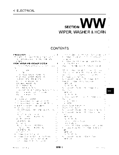
Image preview - the first page of the document

>> Download ww documenatation <<
Text preview - extract from the document
WIPER, WASHER & HORN


K ELECTRICAL

                                                                                                                                                                         A


                                                                                                                                                                         B
                                                                                         SECTION
                                                                                     WIPER, WASHER & HORN                                                                C


                                                                                                                                                                         D


                                                                                                                                                                         E
                                                                    CONTENTS
PRECAUTION ........................................................... 3   .          Only Front Wiper Intermittent Does Not Operate ... 29                              F
 Precautions for Supplemental Restraint System                                        Front Wiper Interval Time Is Not Controlled by Vehi-
 (SRS) "AIR BAG" and "SEAT BELT PRE-TEN-                                              cle Speed ............................................................... 29
                                                                                                                                                                .
 SIONER" ................................................................. 3
                                                                           .          Front Wiper Intermittent Operation Switch Position                                 G
FRONT WIPER AND WASHER SYSTEM ................. 4                          .          Cannot Be Adjusted ............................................... 30     .
 Components Parts and Harness Connector Loca-                                         Wiper Does Not Wipe When Front Washer Operates
 tion .......................................................................... 4
                                                                           .                                                                                    ... 30
                                                                                                                                                                         H
 System Description ................................................. 4    .          After Front Wiper Operate for 10 Seconds, They
    OUT LINE ............................................................. 4
                                                                           .          Stop for 20 Seconds, and After Repeating the Oper-
    LOW SPEED WIPER OPERATION ..................... 5                      .          ations Five Times, They Become Inoperative ....... 31                     .
    HIGH SPEED WIPER OPERATION .................... 5                      .          Front Wiper Does Not Stop .................................... 32         .        I
    INTERMITTENT OPERATION ............................. 5                 .          Removal and Installation of Front Wiper Arms,
    AUTO STOP OPERATION ................................... 6              .          Adjustment of Wiper Arms Stop Location .............. 33                  .
    WASHER OPERATION ........................................ 6            .            REMOVAL .......................................................... 33   .        J
    MIST OPERATION ............................................... 6       .            INSTALLATION .................................................. 33      .
    FAIL-SAFE FUNCTION ........................................ 7          .          Removal and Installation of Front Wiper Drive
    COMBINATION SWITCH READING FUNCTION 8                                  .....      Assembly ............................................................... 33
                                                                                                                                                                .
                                                                                                                                                                         WW
 CAN Communication System Description ............. 10                     .            REMOVAL .......................................................... 33   .
 CAN Communication Unit ..................................... 10           .            INSTALLATION .................................................. 34      .
 Schematic ..............................................................11.          Disassembly and Assembly of Front Wiper Drive
 Wiring Diagram -- WIPER -- ............................... 12             .          Assembly ............................................................... 34
                                                                                                                                                                .        L
 Terminals and Reference Values for BCM ............ 15                    .            DISASSEMBLY .................................................. 34       .
 Terminals and Reference Values for IPDM E/R .... 18                       .            ASSEMBLY ........................................................ 34    .
 How to Proceed With Trouble Diagnosis ............... 19                  .          Washer Nozzle Adjustment ................................... 35           .        M
 Preliminary Check ................................................. 19    .          Washer Tube Layout ............................................. 36       .
    CHECK POWER SUPPLY AND GROUND CIR-                                                Removal and Installation of Front Washer Nozzle... 36
    CUIT ................................................................... 19
                                                                           .          Removal and Installation of Front Washer Tube
 CONSULT-II Functions (BCM) .............................. 20              .          Joint ....................................................................... 36
                                                                                                                                                                .
    CONSULT-II BASIC OPERATION ...................... 20                   .            REMOVAL .......................................................... 36   .
    WORK SUPPORT .............................................. 20         .            INSTALLATION .................................................. 36      .
    DATA MONITOR ................................................ 20       .          Inspection of Washer Nozzle ................................. 37          .
    ACTIVE TEST .................................................... 21    .            CHECK VALVE ................................................... 37      .
 CONSULT-II Functions (IPDM E/R) ...................... 22                 .          Inspection of Front Wiper and Washer Switch Circuit 37                    ...
    CONSULT-II BASIC OPERATION ...................... 22                   .          Removal and Installation of Front Wiper and Washer
    DATA MONITOR ................................................ 22       .          Switch .................................................................... 37
                                                                                                                                                                .
    ACTIVE TEST .................................................... 22    .            REMOVAL .......................................................... 37   .
 Front Wiper Does Not Operate ............................. 23             .            INSTALLATION .................................................. 37      .
 Front Wiper Does Not Return to Stop Position ...... 25                    .          Removal and Installation of Washer Tank ............. 37                  .
 Only Front Wiper Low Does Not Operate ............. 26                    .            REMOVAL .......................................................... 37   .
 Only Front Wiper Hi Does Not Operate ................. 28                 .


Revision: 2006 July                                                           WW-1                                                          2007 FX35/FX45
   INSTALLATION ................................................... 38  .         Removal and Installation of Rear Wiper Motor ......52                   .
 Removal and Installation of Front and Rear Washer                                  REMOVAL ...........................................................52 .
 Pump ..................................................................... 38
                                                                        .           INSTALLATION ...................................................52    .
   REMOVAL .......................................................... 38.         Washer Nozzle Adjustment ....................................53         .
   INSTALLATION ................................................... 38  .         Washer Tube Layout ..............................................53     .
REAR WIPER AND WASHER SYSTEM ................. 39                       .         Removal and Installation of Washer Nozzle ..........54                  .
 Component Parts and Harness Connector Location 39                      ...         REMOVAL ...........................................................54 .
 System Description ................................................ 39 .           INSTALLATION ...................................................54    .
   REAR WIPER OPERATION ............................... 39              .         Check Valve ...........................................................54
                                                                                                                                                          .
   INTERMITTENT OPERATION ........................... 40                .         Inspection of Front Wiper and Washer Switch Circuit                     ...54
   AUTO STOP OPERATION ................................. 40             .         Removal and Installation of Rear Wiper and Washer
   WASHER OPERATION ...................................... 40           .         Switch ....................................................................54
                                                                                                                                                          .
   BCM WIPER SWITCH READING FUNCTION ... 40                                       Removal and Installation of Washer Tank ..............54                .
 Wiring Diagram -- WIP/ R -- ................................ 41        .         Removal and Installation of Front and Rear Washer
 Terminals and Reference Values for BCM ............. 43                .         pump ......................................................................54
                                                                                                                                                          .
 How to Proceed With Trouble Diagnosis ............... 45               .        POWER SOCKET ....................................................55      .
 Preliminary Check ................................................. 45 .         Wiring Diagram -- P/SCKT -- ...............................55           .
   CHECK POWER SUPPLY AND GROUND CIR-                                             Removal and Installation of Front Power Socket
◦ Jabse Service Manual Search 2024 ◦ Jabse Pravopis ◦ onTap.bg ◦ Other service manual resources online : Fixya ◦ eServiceinfo