Service Manuals, User Guides, Schematic Diagrams or docs for : . Car Manuals Infiniti I35 A33 2002-2004 Approved Infiniti I35 2003 gi
<< Back | HomeMost service manuals and schematics are PDF files, so You will need Adobre Acrobat Reader to view : Acrobat Download Some of the files are DjVu format. Readers and resources available here : DjVu Resources
For the compressed files, most common are zip and rar. Please, extract files with Your favorite compression software ( WinZip, WinRAR ... ) before viewing. If a document has multiple parts, You should download all, before extracting.
Good luck. Repair on Your own risk. Make sure You know what You are doing.
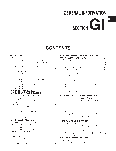
Image preview - the first page of the document

>> Download gi documenatation <<
Text preview - extract from the document
                                                                                              GENERAL INFORMATION


                                                                                                             SECTION                       GI                                MA

                                                                                                                                                                             EM

                                                                                                                                                                             LC

                                                                                                                                                                             EC
                                                                 CONTENTS
                                                                                                                                                                             FE
PRECAUTIONS ...............................................................3            HOW TO PERFORM EFFICIENT DIAGNOSIS
  Precautions ..................................................................3       FOR AN ELECTRICAL INCIDENT ...............................25                         AT
        PRECAUTIONS FOR SUPPLEMENTAL                                                      Work Flow..................................................................25
        RESTRAINT SYSTEM (SRS) AIR BAG AND                                                Incident Simulation Tests...........................................26
        SEAT BELT PRE-TENSIONER .................................3                           INTRODUCTION ......................................................26           AX
        PRECAUTIONS FOR IVIS (INFINITI VEHICLE                                               VEHICLE VIBRATION ..............................................26
        IMMOBILIZER SYSTEM - NATS).................................4                         HEAT SENSITIVE ....................................................27
        GENERAL PRECAUTIONS .........................................4                       FREEZING ..............................................................27       SU
        PRECAUTIONS FOR MULTIPORT FUEL                                                       WATER INTRUSION ................................................28
        INJECTION SYSTEM OR ENGINE CONTROL                                                   ELECTRICAL LOAD .................................................28
        SYSTEM ...................................................................6          COLD OR HOT START UP.......................................28
                                                                                                                                                                             BR
        PRECAUTIONS FOR THREE WAY CATALYST ...........6                                   Circuit Inspection .......................................................28
        PRECAUTIONS FOR HOSES .....................................7                         INTRODUCTION ......................................................28
        PRECAUTIONS FOR ENGINE OILS ...........................7                             TESTING FOR OPENS IN THE CIRCUIT ................29
                                                                                                                                                                             ST
        PRECAUTIONS FOR FUEL ........................................8                       TESTING FOR SHORTS IN THE CIRCUIT ..............30
        PRECAUTIONS FOR AIR CONDITIONING ..................8                                 GROUND INSPECTION ...........................................31
HOW TO USE THIS MANUAL........................................9                                                                                                              RS
                                                                                             VOLTAGE DROP TESTS ..........................................31
HOW TO READ WIRING DIAGRAMS..........................11                                      CONTROL UNIT CIRCUIT TEST ...............................33
  Sample/Wiring Diagram - EXAMPL - ........................11                           HOW TO FOLLOW TROUBLE DIAGNOSES...............35                                     BT
    OPTIONAL SPLICE..................................................12                   How to Follow Test Groups in Trouble Diagnoses....36
        CONTROL UNIT TERMINALS AND REFERENCE                                              Harness Wire Color and Connector Number
        VALUE CHART ........................................................13            Indication....................................................................37   HA
    Description .................................................................14             TYPE 1: HARNESS WIRE COLOR AND
      CONNECTOR SYMBOLS .........................................16                             CONNECTOR NUMBER ARE SHOWN IN
      SWITCH POSITIONS ...............................................17                        ILLUSTRATION .......................................................37       SC
        DETECTABLE LINES AND NON-DETECTABLE                                                     TYPE 2: HARNESS WIRE COLOR AND
        LINES .....................................................................17           CONNECTOR NUMBER ARE SHOWN IN TEXT ........37
        MULTIPLE SWITCH .................................................18               Key to Symbols Signifying Measurements or                                          EL
        REFERENCE AREA .................................................19
                                                                                          Procedures.................................................................38
HOW TO CHECK TERMINAL .......................................21
                                                                                        CONSULT-II CHECKING SYSTEM ...............................40
  Connector and Terminal Pin Kit.................................21
                                                                                          Function and System Application ..............................40
                                                                                                                                                                             IDX
  How to Probe Connectors .........................................21
                                                                                          Nickel Metal Hydride Battery Replacement...............41
     PROBING FROM HARNESS SIDE ............................21
                                                                                          Checking Equipment..................................................41
     PROBING FROM TERMINAL SIDE ...........................22
                                                                                          CONSULT-II Start Procedure ....................................42
  How to Check Enlarged Contact Spring of
                                                                                          CONSULT-II Data Link Connector (DLC) Circuit ......42
  Terminal .....................................................................22
                                                                                             INSPECTION PROCEDURE .....................................42
  Waterproof Connector Inspection ..............................23
                                                                                        IDENTIFICATION INFORMATION ................................44
     RUBBER SEAL INSPECTION ...................................23
                                                                                          Model Variation ..........................................................44
     WIRE SEAL INSPECTION ........................................23
                                                                                             PREFIX AND SUFFIX DESIGNATIONS .....................44
  Terminal Lock Inspection ...........................................24
                                                                                          Identification Number.................................................45
                                                    CONTENTS                                  (Cont'd)
       VEHICLE IDENTIFICATION NUMBER                                                   Garage Jack and Safety Stand .................................49
       ARRANGEMENT .....................................................45             2-pole Lift ...................................................................50
       IDENTIFICATION PLATE..........................................46                Tow Truck Towing ......................................................51
       ENGINE SERIAL NUMBER.......................................46                       VEHICLE RECOVERY (FREEING A STUCK
       AUTOMATIC TRANSAXLE NUMBER ........................46                               VEHICLE)................................................................51
   Dimensions ................................................................47    TIGHTENING TORQUE OF STANDARD BOLTS ........52
   Wheels and Tires.......................................................47        RECOMMENDED CHEMICAL PRODUCTS AND
LIFTING POINTS AND TOW TRUCK TOWING ...........48                                   SEALANTS ....................................................................53
   Preparation ................................................................48   SAE J1930 TERMINOLOGY LIST ................................54
     SPECIAL SERVICE TOOLS ......................................48                    SAE J1930 Terminology List .....................................54
   Board-on Lift ..............................................................48


                                                                                GI-2
          PRECAUTIONS
                                                                   Precautions

         Precautions                                                    NHGI0001
         Observe the following precautions to ensure safe and proper
         servicing. These precautions are not described in each indi-
         vidual section.


                                                                                   MA

                                                                                   EM

         PRECAUTIONS FOR SUPPLEMENTAL RESTRAINT            LC
         SYSTEM (SRS) "AIR BAG" AND "SEAT BELT
         PRE-TENSIONER"                        NHGI0001S01
         The Supplemental Restraint System such as "AIR BAG" and "SEAT             EC
         BELT PRE-TENSIONER" used along with a seat belt, helps to
         reduce the risk or severity of injury to the driver and front passen-
         ger for certain types of collision. This system includes seat belt        FE
         switch inputs and dual stage front air bag modules. The SRS sys-
         tem uses the seat belt switches to determine the front air bag
         deployment, and may only deploy one front air bag, depending on           AT
SGI646
         the severity of a collision and whether the front occupants are
         belted or unbelted. The SRS system composition which is available
         to INFINITI I35 is as follows:                                            AX
◦ Jabse Service Manual Search 2024 ◦ Jabse Pravopis ◦ onTap.bg ◦ Other service manual resources online : Fixya ◦ eServiceinfo