Service Manuals, User Guides, Schematic Diagrams or docs for : . Car Manuals Infiniti Q45 FY33 F50 2001-2006 Approved 2006_Q45 gw
<< Back | HomeMost service manuals and schematics are PDF files, so You will need Adobre Acrobat Reader to view : Acrobat Download Some of the files are DjVu format. Readers and resources available here : DjVu Resources
For the compressed files, most common are zip and rar. Please, extract files with Your favorite compression software ( WinZip, WinRAR ... ) before viewing. If a document has multiple parts, You should download all, before extracting.
Good luck. Repair on Your own risk. Make sure You know what You are doing.
Image preview - the first page of the document

>> Download gw documenatation <<
Text preview - extract from the document
GLASSES, WINDOW SYSTEM & MIRRORS


I BODY

                                                                                                                                                                     A


                            GLASSES, WINDOW SYSTEM & MIRRORS
                                                                                          SECTION                      GW                                            B


                                                                                                                                                                     C


                                                                                                                                                                     D


                                                                                                                                                                     E
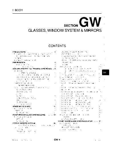
                                                                CONTENTS
PRECAUTIONS ......................................................... 3
                                                                      .            DELAYED POWER OPERATION ...................... 17                        .        F
 Precautions for Supplemental Restraint System                                     ANTI-PINCH SYSTEM ....................................... 17             .
 (SRS) "AIR BAG" and "SEAT BELT PRE-TEN-                                           POWER WINDOW CONTROL BY THE KEY
 SIONER" ................................................................. 3
                                                                      .            CYLINDER SWITCH .......................................... 17            .        G
 Handling for Adhesive and Primer .......................... 3        .            KEYLESS POWER WINDOW DOWN (OPEN)
PREPARATION .......................................................... 4
                                                                      .            OPERATION ....................................................... 17     .
 Special Service Tools .............................................. 4
                                                                      .          Schematic .............................................................. 18.
                                                                                                                                                                     H
 Commercial Service Tools ....................................... 4   .          Wiring Diagram --WINDOW-- .............................. 19                .
SQUEAK AND RATTLE TROUBLE DIAGNOSES..... 5                                       Terminals and Reference Value for BCM .............. 25                    .
 Work Flow ............................................................... 5
                                                                      .          Terminals and Reference Value for Driver Door Con-
   CUSTOMER INTERVIEW .................................... 5          .          trol Unit .................................................................. 25
                                                                                                                                                            .        GW
   DUPLICATE THE NOISE AND TEST DRIVE ...... 6                        .          Terminals and Reference Value for Passenger,
   CHECK RELATED SERVICE BULLETINS .......... 6                       .          Rear LH, RH Door Control Unit ............................. 26             .
   LOCATE THE NOISE AND IDENTIFY THE                                             Trouble Diagnosis Symptom Chart ........................ 27                .        J
   ROOT CAUSE ..................................................... 6 .          Check Communication Signal Circuit .................... 28                 .
   REPAIR THE CAUSE .......................................... 6      .          Check Front Power Window Motor (Driver Side) Cir-
   CONFIRM THE REPAIR ...................................... 7        .          cuit ......................................................................... 30
                                                                                                                                                            .
                                                                                                                                                                     K
 Generic Squeak and Rattle Troubleshooting .......... 7               .          Check Front Power Window Motor (Passenger
   INSTRUMENT PANEL ......................................... 7       .          Side) Circuit ........................................................... 30
                                                                                                                                                            .
   CENTER CONSOLE ............................................ 7      .          Check Rear Power Window Motor (LH or RH) Circuit 31                        ...
   DOORS ................................................................ 7
                                                                      .          Check Limit Switch (Driver Side) ........................... 32            .        L
   TRUNK ................................................................. 8
                                                                      .          Check Limit Switch (Passenger Side) ................... 33                 .
   SUNROOF/HEADLINING .................................... 8          .          Check Limit Switch Circuit (Rear LH or RH) .......... 35                   .
   SEATS .................................................................. 8
                                                                      .          Check Encoder Circuit (Driver Side) ...................... 36              .        M
   UNDERHOOD ...................................................... 8 .          Check Encoder Circuit (Passenger Side) .............. 38                   .
 Diagnostic Worksheet ............................................. 9 .          Check Encoder Circuit (Rear LH or RH) ................ 39                  .
WINDSHIELD GLASS ..............................................11     .          Check Driver Door Control Unit Circuit .................. 41               .
 Removal and Installation ........................................11  .          Check Passenger Door Control Unit Circuit .......... 42                    .
   REMOVAL ...........................................................11
                                                                      .          Check Rear Door Control Unit Circuit .................... 43               .
   INSTALLATION .................................................. 12 .          Check Door Switch ................................................ 44      .
REAR WINDOW GLASS AND MOLDING .............. 14                       .          Rear Power Window Switch Illumination ............... 45                   .
 Removal and Installation ....................................... 14  .            SCHEMATIC ....................................................... 45     .
   REMOVAL .......................................................... 14
                                                                      .            WIRING DIAGRAM -- SW/ILL -- ...................... 46                    .
   INSTALLATION .................................................. 14 .         FRONT DOOR GLASS AND REGULATOR ............ 51                              .
POWER WINDOW SYSTEM ................................... 16            .          Removal and Installation ....................................... 51        .
 Component Parts and Harness Connector Location 16                    ...          DOOR GLASS .................................................... 51       .
 System Description ............................................... 17.            REGULATOR ASSEMBLY ................................. 52                  .
   OUTLINE ............................................................ 17
                                                                      .          Disassembly and Assembly ................................... 53            .
   OPERATIVE CONDITION .................................. 17          .


Revision: 2005 November                                                   GW-1                                                                     2006 Q45
    REGULATOR ASSEMBLY ................................. 53            .           POWER SUPPLY AND GROUND ......................82                   .
  Inspection after Installation .................................... 53.         Component Parts and Harness Connector Location                       ...83
    SETTING OF LIMIT SWITCH ............................. 53           .         Schematic ..............................................................84
                                                                                                                                                      .
    FITTING INSPECTION ....................................... 54      .         Wiring Diagram --MIRROR-- ...............................85          .
REAR DOOR GLASS AND REGULATOR .............. 55                        .         Terminals and Reference Values for Driver Side
  Removal and Installation ....................................... 55  .         Door Mirror Control Unit (LCU03) and Passenger
    DOOR GLASS .................................................... 55 .         Side Door Mirror Control Unit (LCU04) ..................89           .
    REGULATOR ASSEMBLY ................................. 56            .         Terminals and Reference Values for BCM .............89               .
  Inspection after Installation .................................... 58.         Work Flow ..............................................................91
                                                                                                                                                      .
    SETTING OF LIMIT SWITCH ............................. 58           .         Preliminary Check ..................................................91
                                                                                                                                                      .
    FITTING INSPECTION ....................................... 58      .           POWER SUPPLY AND GROUND CIRCUIT
INSIDE MIRROR ...................................................... 59.           INSPECTION ......................................................91.
  Wiring Diagram
◦ Jabse Service Manual Search 2024 ◦ Jabse Pravopis ◦ onTap.bg ◦ Other service manual resources online : Fixya ◦ eServiceinfo