Service Manuals, User Guides, Schematic Diagrams or docs for : . Car Manuals Infiniti Q45 G50 FY33 1994-1996.1998-2000 Approved 2000.5_Q45 at
<< Back | HomeMost service manuals and schematics are PDF files, so You will need Adobre Acrobat Reader to view : Acrobat Download Some of the files are DjVu format. Readers and resources available here : DjVu Resources
For the compressed files, most common are zip and rar. Please, extract files with Your favorite compression software ( WinZip, WinRAR ... ) before viewing. If a document has multiple parts, You should download all, before extracting.
Good luck. Repair on Your own risk. Make sure You know what You are doing.
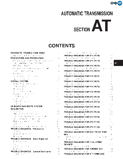
Image preview - the first page of the document

>> Download at documenatation <<
Text preview - extract from the document
                                                                                                                                                                                     EXIT


                                                                                      AUTOMATIC TRANSMISSION


                                                                                                                                      AT
                                                                                                                                                                               GI


                                                                                                        SECTION                                                                MA

                                                                                                                                                                               EM

                                                                                                                                                                               LC
                                                                CONTENTS
                                                                                                                                                                               EC
DIAGNOSTIC TROUBLE CODE INDEX.........................3                                  TCM Terminals and Reference Value........................77
  Alphabetical & P No. Index for DTC ...........................3                      TROUBLE DIAGNOSIS FOR DTC P0705....................81                                   FE
PRECAUTIONS AND PREPARATION............................4                                 Park/Neutral Position (PNP) Switch ..........................81
  Precautions for Supplemental Restraint System                                        TROUBLE DIAGNOSIS FOR DTC P0710....................85
  (SRS) AIR BAG and SEAT BELT                                                            A/T Fluid Temperature Sensor...................................85
  PRE-TENSIONER ......................................................4                TROUBLE DIAGNOSIS FOR DTC P0720....................89
  Precautions for On Board Diagnostic (OBD)                                              Vehicle Speed SensorA/T (Revolution sensor) ........89
  System of A/T and Engine...........................................4                 TROUBLE DIAGNOSIS FOR DTC P0725....................92
                                                                                                                                                                               PD
  Precautions ..................................................................5        Engine Speed Signal .................................................92
  Service Notice or Precautions .....................................6                 TROUBLE DIAGNOSIS FOR DTC P0731....................95                                   FA
  Special Service Tools ..................................................8              A/T 1st Gear Function ...............................................95
OVERALL SYSTEM ......................................................10                TROUBLE DIAGNOSIS FOR DTC P0732..................100
  A/T Electrical Parts Location .....................................10                  A/T 2nd Gear Function ............................................100                 RA
  Circuit Diagram ..........................................................11         TROUBLE DIAGNOSIS FOR DTC P0733..................104
  Wiring Diagram ..........................................................12            A/T 3rd Gear Function.............................................104
  Cross-sectional View .................................................18
                                                                                                                                                                               BR
                                                                                       TROUBLE DIAGNOSIS FOR DTC P0734..................108
  Hydraulic Control Circuits ..........................................19                A/T 4th Gear Function .............................................108
  Shift Mechanism ........................................................20           TROUBLE DIAGNOSIS FOR DTC P0740..................114                                    ST
  Control System ..........................................................29            Torque Converter Clutch Solenoid Valve ................114
  Control Mechanism....................................................31              TROUBLE DIAGNOSIS FOR DTC P0744..................118
  Control Valve .............................................................36          A/T TCC S/V Function (Lock-up).............................118                        RS
ON BOARD DIAGNOSTIC SYSTEM                                                             TROUBLE DIAGNOSIS FOR DTC P0745..................125
DESCRIPTION ...............................................................38            Line Pressure Solenoid Valve .................................125
  Introduction ................................................................38                                                                                              BT
                                                                                       TROUBLE DIAGNOSIS FOR DTC P0750..................129
  OBD-II Function for A/T System................................38                       Shift Solenoid Valve A .............................................129
  One or Two Trip Detection Logic of OBD-II ..............38                           TROUBLE DIAGNOSIS FOR DTC P0755..................133                                    HA
  OBD-II Diagnostic Trouble Code (DTC) ....................38                            Shift Solenoid Valve B .............................................133
  Malfunction Indicator Lamp (MIL)..............................42                     TROUBLE DIAGNOSIS FOR DTC P1705..................137
  CONSULT-II ...............................................................42           Throttle Position Sensor ..........................................137                EL
  Diagnostic Procedure without CONSULT-II...............49                             TROUBLE DIAGNOSIS FOR DTC P1760..................143
TROUBLE DIAGNOSIS - Introduction ........................54                              Overrun Clutch Solenoid Valve ...............................143
  Introduction ................................................................54      TROUBLE DIAGNOSIS FOR BATT/FLUID TEMP
                                                                                                                                                                               IDX
  Diagnostic Worksheet................................................55               SEN ..............................................................................147
  Work Flow..................................................................58          A/T Fluid Temperature Sensor Circuit and TCM
TROUBLE DIAGNOSIS - Basic Inspection ................59                                  Power Source ..........................................................147
  A/T Fluid Check .........................................................59          TROUBLE DIAGNOSIS FOR VHCL SPEED
  Stall Test ....................................................................59    SENMTR .....................................................................151
  Line Pressure Test.....................................................62              Vehicle Speed SensorMTR ....................................151
  Road Test...................................................................64       TROUBLE DIAGNOSIS FOR TURBINE REV ............154
TROUBLE DIAGNOSIS - General Description...........74                                     Turbine Revolution Sensor ......................................154
  Symptom Chart..........................................................74            TROUBLE DIAGNOSIS FOR A/T COMM LINE .........157
                                                                                                                                                                         EXIT


                                                     CONTENTS                                  (Cont'd)
  A/T Communication Line .........................................157                  Shift Lock Control Unit Inspection Table .................192
CONTROL UNIT (RAM), CONTROL UNIT (ROM).....160                                         Component Check ...................................................193
  TCM (Transmission Control Module).......................160                        ON-VEHICLE SERVICE ..............................................195
TROUBLE DIAGNOSES FOR SYMPTOMS...............162                                       Control Valve Assembly and Accumulators.............195
  1. O/D OFF Indicator Lamp Does Not Come On....162                                    Turbine Revolution Sensor Replacement................195
  2. Engine Cannot Be Started In P and N                                               Revolution Sensor Replacement .............................196
  Position ....................................................................163     Rear Oil Seal Replacement.....................................196
  3. In P Position, Vehicle Moves Forward Or                                           Parking Pawl Components Inspection.....................196
  Backward When Pushed .........................................163                    Park/Neutral Position (PNP) Switch Adjustment .....197
  4. In N Position, Vehicle Moves ...........................164                       Manual Control Linkage Adjustment........................197
  5. Large Shock. N -> R Position .......................165                         REMOVAL AND INSTALLATION ................................198
  6. Vehicle Does Not Creep Backward In R                                              Removal...................................................................198
  Position ....................................................................166     Installation................................................................199
  7. Vehicle Does Not Creep Forward In D, 2                                          MAJOR OVERHAUL ...................................................201
  Or 1 Position.........................................................167            Oil Channel ..............................................................203
  8. Vehicle Cannot Be Started From D1 ...................168                          Locations of Needle Bearings, Thrust Washers
  9. A/T Does Not Shift: D1 -> D2 Or Does Not                                          and Snap Rings .......................................................204
  Kickdown: D4 -> D2..................................................169            DISASSEMBLY............................................................205
  10. A/T Does Not Shift: D2 -> D3.............................170                   REPAIR FOR COMPONENT PARTS..........................217
  11. A/T Does Not Shift: D3 -> D4 .............................171                    Oil Pump ..................................................................217
  12. A/T Does Not Perform Lock-up .........................172                        Control Valve Assembly...........................................221
  13. A/T Does Not Hold Lock-up Condition ..............173                            Control Valve Upper Body .......................................227
  14. Lock-up Is Not Released...................................173                    Control Valve Lower Body .......................................232
  15. Engine Speed Does Not Return To Idle (Light                                      Reverse Clutch ........................................................234
  Braking D4 -> D3).....................................................174            High Clutch ..............................................................238
  16. Vehicle Does Not Start From D1 .......................175                        Forward and Overrun Clutches ...............................240
  17. A/T Does Not Shift: D4 -> D3, When                                               Low & Reverse Brake..............................................244
  Overdrive Control Switch ON -> OFF ...............175                                Forward Clutch Drum Assembly..............................248
  18. A/T Does Not Shift: D3 -> 22, When Selector                                      Rear Internal Gear and Forward Clutch Hub ..........250
  Lever D -> 2 Position.........................................176                    Band Servo Piston Assembly ..................................252
  19. A/T Does Not Shift: 22 -> 11, When Selector                                      Parking Pawl Components ......................................256
  Lever 2 -> 1 Position .........................................176                 ASSEMBLY..................................................................258
  20. Vehicle Does Not Decelerate By Engine                                            Assembly (1)............................................................258
  Brake........................................................................177     Adjustment ...............................................................266
  21. TCM Self-diagnosis Does Not Activate (Park/                                      Assembly (2)............................................................268
  Neutral Position, Overdrive Control and Throttle                                   SERVICE DATA AND SPECIFICATIONS (SDS) ........276
  Position Switch Circuit Checks)...............................177                    General Specifications.............................................276
TROUBLE DIAGNOSES - A/T Shift Lock System ...183                                       Specifications and Adjustment.................................276
  A/T Shift Lock System .............................................183               Shift Solenoid Valves...............................................280
  Wiring Diagram ........................................................184           Solenoid Valves .......................................................280
  Diagnostic Procedure 1 ...........................................185                A/T Fluid Temperature Sensor.................................280
  Diagnostic Procedure 2 ...........................................189                Revolution Sensor ...................................................280
  Shift Lock Control Unit Inspection ...........................192                    Dropping Resistor ....................................................280

            When you read wiring diagrams:
◦ Jabse Service Manual Search 2024 ◦ Jabse Pravopis ◦ onTap.bg ◦ Other service manual resources online : Fixya ◦ eServiceinfo