Service Manuals, User Guides, Schematic Diagrams or docs for : . Car Manuals Infiniti Q45 G50 FY33 1994-1996.1998-2000 Approved 2000.0_Q45 ha
<< Back | HomeMost service manuals and schematics are PDF files, so You will need Adobre Acrobat Reader to view : Acrobat Download Some of the files are DjVu format. Readers and resources available here : DjVu Resources
For the compressed files, most common are zip and rar. Please, extract files with Your favorite compression software ( WinZip, WinRAR ... ) before viewing. If a document has multiple parts, You should download all, before extracting.
Good luck. Repair on Your own risk. Make sure You know what You are doing.
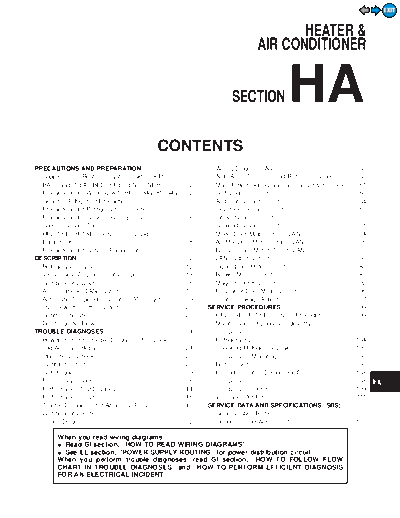
Image preview - the first page of the document

>> Download ha documenatation <<
Text preview - extract from the document
                                                                                                                                                                           EXIT


                                                                                                                  HEATER &
                                                                                                           AIR CONDITIONER


                                                                                                                           HA
                                                                                                                                                                     GI


                                                                                               SECTION                                                               MA

                                                                                                                                                                     EM

                                                                                                                                                                     LC
                                                              CONTENTS
                                                                                                                                                                     EC
PRECAUTIONS AND PREPARATION............................2                             Wiring Diagram - A/C - ..............................................53
  Supplemental Restraint System (SRS) AIR                                            Auto Amp. Terminals and Reference Value...............58
  BAG and SEAT BELT PRE-TENSIONER...............2                                    Main Power Supply and Ground Circuit Check ........61                           FE
  Precautions for Working with HFC-134a (R-134a) .....2                              Self-diagnosis Circuit .................................................63
  General Refrigerant Precautions .................................3                 Ambient Sensor Circuit..............................................64
  Precautions for Refrigerant Connection ......................3                     In-vehicle Sensor Circuit............................................67
                                                                                                                                                                     AT
  Precautions for Servicing Compressor........................6                      Intake Sensor Circuit .................................................70
  Special Service Tools ..................................................7          Sunload Sensor Circuit..............................................71          PD
  HFC-134a (R-134a) Service Tools and                                                Mode Door Motor Circuit (LAN).................................74
  Equipment....................................................................8     Air Mix Door Motor Circuit (LAN) ..............................76
  Precautions for Service Equipment ...........................10                    Bi-level Door Motor Circuit (LAN)..............................78               FA
DESCRIPTION ...............................................................12        LAN System Circuit ...................................................80
  Refrigeration Cycle ....................................................12         Intake Door Motor Circuit ..........................................83
  V-6 Variable Displacement Compressor....................13                         Blower Motor Circuit ..................................................87       RA
  Component Layout ....................................................16            Magnet Clutch Circuit ................................................92
  Air Conditioner LAN System......................................17                 Rear Vent Door Motor Circuit ....................................96
                                                                                                                                                                     BR
  Automatic Temperature Control (ATC) System .........19                             Control Linkage Adjustment.......................................97
  Overview of Control System......................................20               SERVICE PROCEDURES .............................................99
  Control Operation ......................................................20         HFC-134a (R-134a) Service Procedure ....................99                      ST
  Discharge Air Flow.....................................................22          Maintenance of Lubricant Quantity in
TROUBLE DIAGNOSES ...............................................24                  Compressor .............................................................102
  How to Perform Trouble Diagnoses for Quick                                         Refrigerant Lines .....................................................104      RS
  and Accurate Repair ..................................................24           Checking Refrigerant Leaks ....................................105
  Operational Check .....................................................25          Compressor Mounting .............................................108
  Symptom Chart..........................................................28          Belt Tension .............................................................108
                                                                                                                                                                     BT
  Self-diagnosis ............................................................29      Fast Idle Control Device (FICD) ..............................108
  Preliminary Check......................................................36          Compressor .............................................................108
  Performance Test Diagnoses ....................................44                  Compressor Clutch ..................................................109
  Performance Chart ....................................................46           Ventilation Air Filter.................................................. 111
  Trouble Diagnoses for Abnormal Pressure ...............47                        SERVICE DATA AND SPECIFICATIONS (SDS) ........113                                 EL
  Component Location..................................................50             General Specifications.............................................113
  Circuit Diagram ..........................................................52       Inspection and Adjustment ......................................113
                                                                                                                                                                     IDX
           When you read wiring diagrams:
◦ Jabse Service Manual Search 2024 ◦ Jabse Pravopis ◦ onTap.bg ◦ Other service manual resources online : Fixya ◦ eServiceinfo