Service Manuals, User Guides, Schematic Diagrams or docs for : . Car Manuals Jeep Cherokee XJ 1988-1989.1993-1995 Approved 1994 XJ Jeep Cherokee 94XJ_8R
<< Back | HomeMost service manuals and schematics are PDF files, so You will need Adobre Acrobat Reader to view : Acrobat Download Some of the files are DjVu format. Readers and resources available here : DjVu Resources
For the compressed files, most common are zip and rar. Please, extract files with Your favorite compression software ( WinZip, WinRAR ... ) before viewing. If a document has multiple parts, You should download all, before extracting.
Good luck. Repair on Your own risk. Make sure You know what You are doing.
Image preview - the first page of the document

>> Download 94XJ_8R documenatation <<
Text preview - extract from the document
J                                                                                                      POWER SEATS           8R - 1

                                                     POWER SEATS

                                                             CONTENTS
                                                              page                                                              page

DIAGNOSIS . . . . . . . . . . . . . . . . . . . . . . . . . . . . . 1   POWER SEAT MOTOR REPLACEMENT . . . . . . . 2
GENERAL . . . . . . . . . . . . . . . . . . . . . . . . . . . . . . 1   SWITCH TESTING . . . . . . . . . . . . . . . . . . . . . . . 2

GENERAL                                                                 ward-rearward motor. The motor is grounded
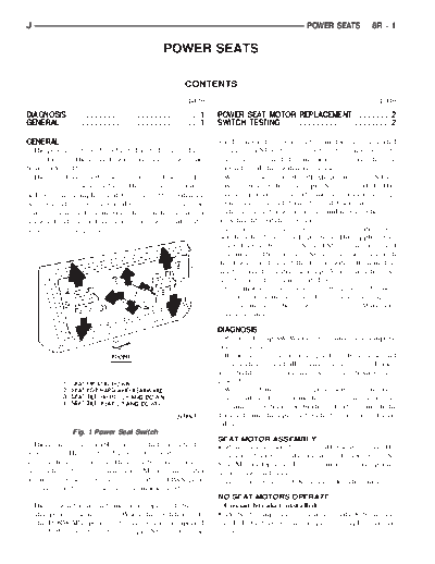
  The power seat can be adjusted in 6 different direc-                  through pin S4 and the contacts of the back switch to
tions (Fig. 1). The control switch is on the lower out-                 pin 2 and to ground. The motor runs to drive the seat
board side of the seat.                                                 forward until the switch is released.
  The front lever on the switch raises or lowers (tilts)                  With the switch in the REAR position, pin S4 re-
the front of the seat cushion. The center lever raises                  ceives battery voltage and pin S3 is grounded. This
or lowers the complete seat by moving the switch up                     reversed polarity causes the motor to run in the op-
or down. The center lever also moves the seat for-                      posite direction and drive the seat backward.
ward or rearward by moving the switch forward or                          The front motor works in a similar way when the
rearward. The rear lever raises or lowers (tilts) the                   front height switch is operated.
back of the seat cushion.                                                 To raise the entire seat, the center position seat
                                                                        switch is held in the UP position. This applies bat-
                                                                        tery voltage to both pins S1 and S5 and the front and
                                                                        rear motors. Pins S2 and S6 are grounded through
                                                                        the down switches and the lower switch. Both motors
                                                                        run to drive the entire seat up. A similar action oc-
                                                                        curs to move the entire seat down.
                                                                          Each motor contains a self-resetting circuit breaker
                                                                        to protect it from overload. Consecutive or frequent
                                                                        resetting must not be allowed to continue. Make nec-
                                                                        essary repairs.

                                                                        DIAGNOSIS
                                                                          Refer to Group 8W-Wiring Diagrams for a complete
                                                                        circuit diagram.
                                                                          Before any testing is attempted the battery should
                                                                        be fully charged and all connections and pins cleaned
                                                                        and tightened to insure proper continuity and
                                                                        grounds.
                                                                          With the dome light on, apply switch in direction
                                                                        of the failure. If the dome light dims, the seat may
                                                                        be jamming. Check for binding. If the dome light
                                                                        does not dim, then proceed with the following electri-
                                                                        cal tests.
                  Fig. 1 Power Seat Switch
                                                                        SEAT MOTOR ASSEMBLY
  There are 3 reversible motors that operate the
◦ Jabse Service Manual Search 2024 ◦ Jabse Pravopis ◦ onTap.bg ◦ Other service manual resources online : Fixya ◦ eServiceinfo