Service Manuals, User Guides, Schematic Diagrams or docs for : . Car Manuals Jeep Cherokee XJ 1988-1989.1993-1995 Approved 1995 XJ Jeep Cherokee 95XJ_16
<< Back | HomeMost service manuals and schematics are PDF files, so You will need Adobre Acrobat Reader to view : Acrobat Download Some of the files are DjVu format. Readers and resources available here : DjVu Resources
For the compressed files, most common are zip and rar. Please, extract files with Your favorite compression software ( WinZip, WinRAR ... ) before viewing. If a document has multiple parts, You should download all, before extracting.
Good luck. Repair on Your own risk. Make sure You know what You are doing.
Image preview - the first page of the document

>> Download 95XJ_16 documenatation <<
Text preview - extract from the document
J                                                                                     PROPELLER SHAFTS           16 - 1

                                        PROPELLER SHAFTS

                                                      CONTENTS

                                                       page                                                        page

GENERAL INFORMATION . . . . . . . . . . . . . . . . . . 1       TORQUE SPECIFICATIONS . . . . . . . . . . . . . . . . 15
SERVICE DIAGNOSIS . . . . . . . . . . . . . . . . . . . . . 3   UNIVERSAL JOINT REPLACEMENT . . . . . . . . . 10
SERVICE PROCEDURES . . . . . . . . . . . . . . . . . . . 8


                                           GENERAL INFORMATION

PROPELLER SHAFTS                                                  The propeller shaft must operate through con-
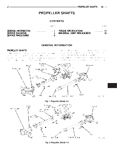
  The function of a propeller shaft is to transmit              stantly changing relative angles between the trans-
power from one point to another. The shaft is de-               mission and axle. It must also be capable of changing
signed to send torque from the transmission (transfer           length while transmitting torque. The axle rides sus-
case on 4WD vehicles) to the axle (Fig. 1,2).                   pended by springs in a floating motion. The propeller


                                                Fig. 1 Propeller Shafts XJ


                                                Fig. 2 Propeller Shafts YJ
16 - 2    PROPELLER SHAFTS                                                                              J

shaft must be able to change operating angles when
going over various road surfaces. This is done
through universal joints, which permit the propeller
shaft to operate at different angles. The slip joints (or
yokes) permit contraction or expansion (Fig. 1,2).
  Tubular propeller shafts are balanced by the man-
ufacturer with weights spot welded to the tube.
  The propeller shaft is designed and built with the
yoke lugs in line with each other which is called
phasing. This design produces the smoothest running
condition, an out of phase shaft can cause a vibra-
tion.
  Before undercoating a vehicle, the propeller
shaft and the U-joints should be covered. This
will prevent the undercoating from causing an
unbalanced condition and vibration.

CAUTION: Use exact replacement hardware for at-
taching the propeller shafts. The specified torque
must always be applied when tightening the fasten-
ers.
                                                              Fig. 3 Single Cardan Universal Joint

UNIVERSAL JOINTS
  Two different types of U-joints are used with the
propeller shafts:
◦ Jabse Service Manual Search 2024 ◦ Jabse Pravopis ◦ onTap.bg ◦ Other service manual resources online : Fixya ◦ eServiceinfo