Service Manuals, User Guides, Schematic Diagrams or docs for : . Car Manuals Jeep Cherokee XJ 1988-1989.1993-1995 Approved 1995 XJ Jeep Cherokee 95XJ_8F
<< Back | HomeMost service manuals and schematics are PDF files, so You will need Adobre Acrobat Reader to view : Acrobat Download Some of the files are DjVu format. Readers and resources available here : DjVu Resources
For the compressed files, most common are zip and rar. Please, extract files with Your favorite compression software ( WinZip, WinRAR ... ) before viewing. If a document has multiple parts, You should download all, before extracting.
Good luck. Repair on Your own risk. Make sure You know what You are doing.
Image preview - the first page of the document

>> Download 95XJ_8F documenatation <<
Text preview - extract from the document
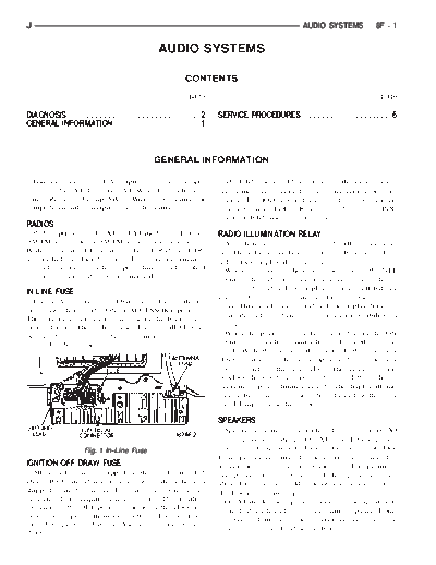
J                                                                                                 AUDIO SYSTEMS          8F - 1

                                                  AUDIO SYSTEMS

                                                             CONTENTS

                                                              page                                                         page

DIAGNOSIS . . . . . . . . . . . . . . . . . . . . . . . . . . . . . 2   SERVICE PROCEDURES          ................... 6
GENERAL INFORMATION . . . . . . . . . . . . . . . . . . 1


                                                 GENERAL INFORMATION

  Following are general descriptions of major compo-                      The IOD fuse should be checked if the radio station
nents used in XJ (Cherokee)/YJ (Wrangler) audio sys-                    preset memory or clock functions are erratic or inop-
tems. Refer to Group 8W - Wiring Diagrams for                           erative. The IOD fuse is located in the Power Distri-
complete circuit descriptions and diagrams.                             bution Center (PDC). Refer to underside of PDC
                                                                        cover for IOD fuse identification.
RADIOS
  Radio options for the XJ and YJ models include an                     RADIO ILLUMINATION RELAY
AM/FM stereo or an AM/FM stereo/cassette receiver.                        All radios are connected to a radio illumination re-
Both units are Electronically-Tuned Radios (ETR)                        lay. The relay controls the source of battery feed for
and include a clock function. For more information                      radio/clock display illumination.
on radio features, setting procedures, and control                        When the park and headlamp switch is in the OFF
functions refer to the owner's manual.                                  position, the radio illumination relay remains de-en-
                                                                        ergized. The radio/clock display receives full battery
IN-LINE FUSE
                                                                        voltage through the normally closed contacts of the
  Each radio receives fused battery feed when the ig-
                                                                        relay. This results in the radio/clock display being il-
nition switch is in the ON or ACCESSORY position.
                                                                        luminated at full brightness for easier visibility in
There is an additional in-line fuse in the back of the
radio chassis. The in-line fuse (Fig. 1) will blow to                   daylight.
protect the vehicle electrical system in the event of                     When the park and headlamp switch is in the ON
internal radio failure.                                                 position, the radio illumination relay coil is ener-
                                                                        gized. With the relay coil energized, the normally
                                                                        closed contacts of the relay open, and the normally
                                                                        open contacts of the relay close. This causes the ra-
                                                                        dio/clock display to receive battery feed through the
                                                                        instrument panel dimmer switch. The display illumi-
                                                                        nation brightness can now be adjusted with other
                                                                        panel lamps for night visibility.

                                                                        SPEAKERS
                                                                          Speaker system options include two, four or six (XJ
                                                                        only) speaker locations. On XJ model two-speaker
                      Fig. 1 In-Line Fuse                               systems, one speaker is located in each front door.
                                                                        Four-speaker systems add one speaker at each end of
IGNITION-OFF DRAW FUSE                                                  a rear-mounted overhead sound bar. The premium
  All vehicles are equipped with an Ignition-Off                        six-speaker option upgrades all the speakers in the
Draw (IOD) fuse that is removed when the vehicle is                     above locations, and adds one tweeter at each end of
shipped from the factory. This fuse feeds various ac-                   the lower instrument panel.
cessories that require current when the ignition                          On YJ model two-speaker systems, one speaker is
switch is in the OFF position, including the clock and
                                                                        located at each end of the instrument panel. Four-
radio station preset memory functions. The fuse is re-
                                                                        speaker systems add one speaker at each end of a
moved to prevent battery discharge during vehicle
                                                                        rear-mounted overhead sound bar.
storage.
8F - 2    AUDIO SYSTEMS                                                                                          J

ANTENNA                                                       External suppression devices that are serviceable
  All models use a fixed-length stainless steel rod-        and should be checked in the case of RFI or EMI
type antenna mast, installed at the right front (fend-      noise complaints include the following:
er on XJ, cowl side on YJ) of the vehicle. The
◦ Jabse Service Manual Search 2024 ◦ Jabse Pravopis ◦ onTap.bg ◦ Other service manual resources online : Fixya ◦ eServiceinfo