Service Manuals, User Guides, Schematic Diagrams or docs for : . Car Manuals Jeep Cherokee XJ 1988-1989.1993-1995 Approved 1995 XJ Jeep Cherokee 95XJ_8R
<< Back | HomeMost service manuals and schematics are PDF files, so You will need Adobre Acrobat Reader to view : Acrobat Download Some of the files are DjVu format. Readers and resources available here : DjVu Resources
For the compressed files, most common are zip and rar. Please, extract files with Your favorite compression software ( WinZip, WinRAR ... ) before viewing. If a document has multiple parts, You should download all, before extracting.
Good luck. Repair on Your own risk. Make sure You know what You are doing.
Image preview - the first page of the document
>> Download 95XJ_8R documenatation <<
Text preview - extract from the document
J POWER SEATS 8R - 1
POWER SEATS
CONTENTS
page page
DIAGNOSIS . . . . . . . . . . . . . . . . . . . . . . . . . . . . . 2 SERVICE PROCEDURES ................... 3
GENERAL INFORMATION . . . . . . . . . . . . . . . . . . 1
GENERAL INFORMATION
A six-way driver's side power seat is an available
option on XJ (Cherokee) models. The power seat sys-
tem receives battery feed through fuse 6 in the power
distribution center and circuit breaker 16 in the fuse-
block module at all times.
Following are general descriptions of the major
components in the power seat system. Refer to Group
8W - Wiring Diagrams for complete circuit descrip-
tions and diagrams.
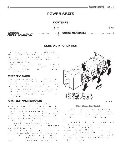
POWER SEAT SWITCH
The power seat can be adjusted in six different
ways using the power seat switch (Fig. 1). The switch
is located on the lower outboard side of the seat
cushion. Refer to the owner's manual for more infor-
mation on power seat switch functions and seat ad-
justing procedures. The individual switches cannot be
repaired. If one switch fails, the entire switch module
must be replaced.
POWER SEAT ADJUSTER/MOTORS
There are three reversible motors that operate the
power seat adjuster. The motors are connected to Fig. 1 Power Seat Switch
worm-drive gearboxes in the adjuster by drive cables. juster is reached. When the switch is moved in the
The front and rear of a seat are operated by differ- opposite direction, the battery feed and ground path
ent motors. They can be raised or lowered indepen-
to the motor(s) are reversed through the switch con-
dently of each other. When the center seat switch is
tacts. This causes the motor to run in the opposite di-
pushed to the UP or DOWN position, both front and
rection.
rear motors operate in unison, moving the entire seat
Each motor contains a self-resetting circuit breaker
up or down. The forward-rearward motor is operated
by pushing the center seat switch to the FORWARD to protect it from overload. Consecutive or frequent
or REARWARD position. resetting must not be allowed to continue or the mo-
When a switch is actuated, battery feed and a tors may be damaged. Make the necessary repairs.
ground path are applied through the switch contacts The power seat adjuster and motors can not be re-
to the motor(s). The motor(s) operate to move the paired, and are serviced only as a complete unit. If
seat in the selected direction until the switch is re- any component in this unit should fail, the entire as-
leased, or until the travel limit of the power seat ad- sembly must be replaced.
8R - 2 POWER SEATS J
DIAGNOSIS
Before any testing is attempted the battery should (3) Check for continuity between black wire at
be fully charged and all connections and pins cleaned switch connector and a good ground. There should be
and tightened to ensure proper continuity and continuity. If OK, go to next step. If not OK, repair
grounds. wiring to ground.
With the dome lamp on, apply switch in direction (4) See diagnosis for Power Seat Switch. If switch
of the failure. If the dome lamp dims, the seat may continuity checks OK, replace faulty motor/adjuster
be jamming. Check for binding or obstructions. If the assembly. If switch continuity is not OK, replace
dome lamp does not dim, then proceed with the fol- faulty switch.
lowing electrical tests.
POWER SEAT SWITCH
POWER SEAT ADJUSTER/MOTORS To check the power seat switch, remove the switch
Operate the power seat switch to move all three from its mounting position. Use an ohmmeter and
seat motors. The seat should move in all directions. see the Power Seat Switch Continuity chart. Deter-
If not OK, proceed as follows. If one or more motors mine if switch continuity is correct. If OK, see Power
operate, see diagnosis for Power Seat Switch. Seat Adjuster/Motors diagnosis. If not OK, replace
(1) Check circuit breaker 16 in the fuseblock mod- faulty switch assembly.
ule. If OK, go to next step. If not OK, replace circuit
breaker.
(2) Remove switch mounting screws and check for
battery voltage at red wire at switch connector. If
OK, go to next step. If not OK, repair wiring to cir-
cuit breaker.
POWER SEAT SWITCH CONTINUITY
J POWER SEATS 8R - 3
SERVICE PROCEDURES
POWER SEAT SWITCH REMOVE/INSTALL POWER SEAT ADJUSTER/MOTORS REMOVE/
(1) Disconnect battery negative cable. INSTALL
(2) Reach under seat and release switch and bezel (1) Disconnect battery negative cable.
retainer snap clips (Fig. 2), while pulling gently on (2) Remove 4 bolts securing seat adjuster to floor
switch and bezel assembly. (Fig. 3).
Fig. 2 Power Seat Switch Remove/Install Fig. 3 Power Seat Adjuster Remove/Install
(3) Disconnect power seat feed wiring connector.
(3) Pull switch, bezel, and retainer out from seat
(4) Remove 4 bolts securing power seat adjuster/
frame far enough to access multiple terminal block.
motor assembly to seat cushion frame.
Carefully release locking tabs and separate switch (5) Disconnect wiring from power seat switch to
retainer and switch bezel from switch body. power seat motors and remove power seat adjuster/
(4) Carefully release locking tabs securing multiple motor assembly.
terminal block to switch and remove switch. (6) Reverse removal procedures to install. Tighten
(5) Reverse removal procedures to install. seat mounting hardware to 34 N m (25 ft. lbs.)
torque.
◦ Jabse Service Manual Search 2026 ◦ Jabse Pravopis ◦ onTap.bg ◦ Other service manual resources online : Fixya ◦ eServiceinfo