Service Manuals, User Guides, Schematic Diagrams or docs for : . Car Manuals Mitsubishi Eclipse & Spyder 2000-2006 Approved Mitsubishi Eclipse 2006 GR00005900A-13B
<< Back | HomeMost service manuals and schematics are PDF files, so You will need Adobre Acrobat Reader to view : Acrobat Download Some of the files are DjVu format. Readers and resources available here : DjVu Resources
For the compressed files, most common are zip and rar. Please, extract files with Your favorite compression software ( WinZip, WinRAR ... ) before viewing. If a document has multiple parts, You should download all, before extracting.
Good luck. Repair on Your own risk. Make sure You know what You are doing.
Image preview - the first page of the document
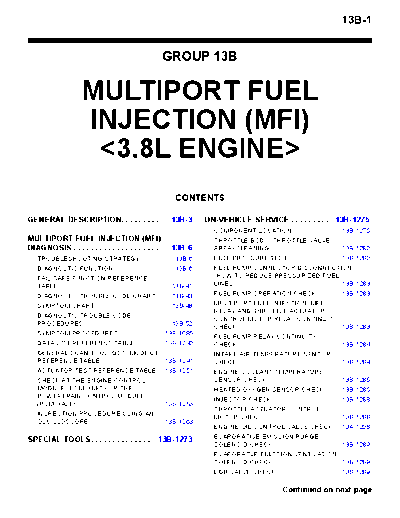
>> Download GR00005900A-13B documenatation <<
Text preview - extract from the document
                                                                                                                                           13B-1


                                                                    GROUP 13B


                         MULTIPORT FUEL
                         INJECTION (MFI)
                          <3.8L ENGINE>
                                                                     CONTENTS

GENERAL DESCRIPTION. . . . . . . . .                                 13B-3    ON-VEHICLE SERVICE . . . . . . . . . 13B-1275
                                                                                COMPONENT LOCATION . . . . . . . . . . . . . 13B-1275
MULTIPORT FUEL INJECTION (MFI)                                                  THROTTLE BODY (THROTTLE VALVE
DIAGNOSIS . . . . . . . . . . . . . . . . . . . .                    13B-6      AREA) CLEANING . . . . . . . . . . . . . . . . . . . 13B-1280
   TROUBLESHOOTING STRATEGY . . . . . .                               13B-6     FUEL PRESSURE TEST . . . . . . . . . . . . . . 13B-1280
   DIAGNOSTIC FUNCTION . . . . . . . . . . . . .                      13B-6     FUEL PUMP CONNECTOR DISCONNECTION
   FAIL-SAFE FUNCTION REFERENCE                                                 (HOW TO REDUCE PRESSURIZED FUEL
   TABLE. . . . . . . . . . . . . . . . . . . . . . . . . . . . .    13B-41     LINES) . . . . . . . . . . . . . . . . . . . . . . . . . . . . . 13B-1283
   DIAGNOSTIC TROUBLE CODE CHART . .                                 13B-43     FUEL PUMP OPERATION CHECK . . . . . . 13B-1283
   SYMPTOM CHART. . . . . . . . . . . . . . . . . . .                13B-48     MULTIPORT FUEL INJECTION (MFI)
                                                                                RELAY AND THROTTLE ACTUATOR
   DIAGNOSTIC TROUBLE CODE
                                                                                CONTROL MOTOR RELAY CONTINUITY
   PROCEDURES. . . . . . . . . . . . . . . . . . . . . .             13B-52
                                                                                CHECK . . . . . . . . . . . . . . . . . . . . . . . . . . . . 13B-1283
   SYMPTOM PROCEDURES . . . . . . . . . . . . 13B-1085
                                                                                FUEL PUMP RELAY CONTINUITY
   DATA LIST REFERENCE TABLE . . . . . . . 13B-1230                             CHECK . . . . . . . . . . . . . . . . . . . . . . . . . . . . 13B-1284
   GENERAL SCAN TOOL (GST) MODE 01                                              INTAKE AIR TEMPERATURE SENSOR
   REFERENCE TABLE . . . . . . . . . . . . . . . . . 13B-1241                   CHECK . . . . . . . . . . . . . . . . . . . . . . . . . . . . 13B-1284
   ACTUATOR TEST REFERENCE TABLE. . 13B-1251                                    ENGINE COOLANT TEMPERATURE
   CHECK AT THE ENGINE CONTROL                                                  SENSOR CHECK . . . . . . . . . . . . . . . . . . . . 13B-1285
   MODULE (ECM)  OR THE                                                    HEATED OXYGEN SENSOR CHECK . . . . 13B-1285
   POWERTRAIN CONTROL MODULE                                                    INJECTOR CHECK . . . . . . . . . . . . . . . . . . . 13B-1288
   (PCM)  . . . . . . . . . . . . . . . . . . . . . . . . 13B-1253
                                                                                THROTTLE ACTUATOR CONTROL
   INSPECTION PROCEDURE USING AN                                                MOTOR CHECK . . . . . . . . . . . . . . . . . . . . . 13B-1288
   OSCILLOSCOPE . . . . . . . . . . . . . . . . . . . . 13B-1263
                                                                                ENGINE OIL CONTROL VALVE CHECK . . 13A-1208
                                                                                EVAPORATIVE EMISSION PURGE
SPECIAL TOOLS. . . . . . . . . . . . . .                       13B-1273
                                                                                SOLENOID CHECK . . . . . . . . . . . . . . . . . . 13B-1289
                                                                                EVAPORATVE EMISSION VENTILATION
                                                                                SOLENOID CHECK . . . . . . . . . . . . . . . . . . 13B-1289
                                                                                EGR VALVE CHECK. . . . . . . . . . . . . . . . . . 13B-1289

                                                                                                                Continued on next page
13B-2


INJECTOR . . . . . . . . . . . . . . . . . . .   13B-1290   FASTENER TIGHTENING
   REMOVAL AND INSTALLATION . . . . . . . . 13B-1290        SPECIFICATIONS . . . . . . . . . . . . . 13B-1297
                                                              FASTENER TIGHTENING
THROTTLE BODY ASSEMBLY . .                       13B-1293     SPECIFICATIONS. . . . . . . . . . . . . . . . . . . . 13B-1297
   REMOVAL AND INSTALLATION . . . . . . . . 13B-1293          GENERAL SPECIFICATIONS . . . . . . . . . . 13B-1297
                                                              SERVICE SPECIFICATIONS . . . . . . . . . . . 13B-1299
ENGINE CONTROL MODULE (ECM)                                   SEALANT AND ADHESIVE . . . . . . . . . . . . 13B-1299
AND POWERTRAIN CONTROL
MODULE (PCM). . . . . . . . . . . . . . . 13B-1295
   REMOVAL AND INSTALLATION . . . . . . . . 13B-1295
                           MULTIPORT FUEL INJECTION (MFI) <3.8L ENGINE>
                                           GENERAL DESCRIPTION
                                                                                                         13B-3
                                GENERAL DESCRIPTION
                                                                                                       M1131000102257
.                                                         .


The Multiport Fuel Injection System consists of sen-      THROTTLE VALVE OPENING CONTROL
sors which detect the engine conditions, the ENGINE       This system electrically controls the opening of the
CONTROL MODULE (ECM)  POWERTRAIN                     throttle valve. The ECM  or the PCM
CONTROL MODULE (PCM)  which controls                 detects the amount of travel of the accelerator pedal
the system based on signals from these sensors,           via the accelerator pedal position sensor, and con-
and actuators which operate under the control of the      trols the actuation of the throttle actuator control
ECM  or the PCM .                               motor, which is mounted on the throttle body, in order
The ECM  or the PCM  carries out activ-         to attain the target throttle valve opening that has
ities such as fuel injection control, idle air control,   been predetermined in accordance with driving con-
and ignition timing control.                              ditions.
In addition, the ECM  or the PCM  is
equipped with several diagnostic test modes which         .


simplify troubleshooting when a problem develops.         IDLE AIR CONTROL
                                                          The idle speed is kept at the optimum speed by con-
                                                          trolling the amount of air that passes through the
.


FUEL INJECTION CONTROL
                                                          throttle valve in accordance with changes in idling
The injector drive times and injector timing are con-     conditions and engine load during idling.
trolled so that the optimum air/fuel mixture is sup-      The ECM  or the PCM  drives the throt-
plied to the engine to correspond to the                  tle actuator control motor to keep the engine running
continually-changing engine operation conditions.         at the pre-set idle target speed in accordance with
A single injector is mounted at the intake port of each   the engine coolant temperature and A/C and other
cylinder. Fuel is sent under pressure from the fuel       electrical load. In addition, when the air conditioning
tank to the fuel injectors by the fuel pump, with the     switch is turned off and on while the engine is idling,
pressure being regulated by the fuel pressure regula-     the throttle actuator control motor adjusts the throttle
tor. The regulated fuel is distributed to each of the     valve pass-through air amount according to the
injectors.                                                engine load conditions to avoid fluctuations in the
Fuel injection is normally carried out once for each      engine speed.
cylinder for every two rotations of the crankshaft.
The firing order is 1-2-3-4-5-6. Each cylinder has a      .


dedicated fuel injector. This is called multiport.        IGNITION TIMING CONTROL
The ECM  or the PCM  provides a richer          The ignition power transistor located in the ignition
air/fuel mixture by carrying out "open-loop" control      primary circuit turns ON and OFF to control the pri-
when the engine is cold or operating under high load      mary current flow to the ignition coil. This controls the
conditions in order to maintain engine perfor-            ignition timing to provide the optimum ignition timing
mance.In addition, when the engine is under normal        with respect to the engine operating conditions. The
operating temperature after warming-up, the ECM           ignition timing is determined by the ECM  or
 or the PCM  controls the air/fuel mixture      the PCM  from engine speed, intake air vol-
by using the heated oxygen sensor signal to carry         ume, engine coolant temperature, and atmospheric
out "closed-loop" control. The closed-loop control        pressure.
achieves the theoretical air/fuel mixture ratio where     .


the catalytic converter can obtains the maximum
cleaning performance.


                                   TSB Revision
13B-4                            MULTIPORT FUEL INJECTION (MFI) <3.8L ENGINE>
                                                 GENERAL DESCRIPTION

DIAGNOSTIC TEST MODE                                       A/C Compressor Clutch Relay Control
◦ Jabse Service Manual Search 2026 ◦ Jabse Pravopis ◦ onTap.bg ◦ Other service manual resources online : Fixya ◦ eServiceinfo