Service Manuals, User Guides, Schematic Diagrams or docs for : . Car Manuals Nissan 300ZX 1984-1985,1988,1990,1994-1996 Approved 1984 Propeller Shaft & Differential Carrier

<< Back | Home

Most service manuals and schematics are PDF files, so You will need Adobre Acrobat Reader to view : Acrobat Download Some of the files are DjVu format. Readers and resources available here : DjVu Resources
For the compressed files, most common are zip and rar. Please, extract files with Your favorite compression software ( WinZip, WinRAR ... ) before viewing. If a document has multiple parts, You should download all, before extracting.
Good luck. Repair on Your own risk. Make sure You know what You are doing.


Image preview - the first page of the document
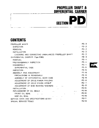
Propeller Shaft & Differential Carrier


>> Download Propeller Shaft & Differential Carrier documenatation <<

Text preview - extract from the document
                                              PROPELLER SHAFT &
                                            DIFFERENTIAL CARRIER
I


                                                SECTION   PD
CONTENTS
PROPELLER SHAFT                                              PD- 2
  INSPECTION                                                 PD-   2
  REMOVAL                                                    PD-   2
    I NSTALLATION                                            PD-   2
    CHECKING AND CORRECTING UNBALANCED PROPELLER SHAFT       PD-   2
DIFFERENTIAL CARRIER (Type R200)                             PD-   3
  REMOVAL                                                    PD-   4
  PRE-DISASSEMBLY INSPECTION                                 PD-   4
  DISASSEMBLY                                                PD-   4
    DIFFERENTIAL CASE                                        PD-   5
  INSPECTION.                                                PD-   5
  ASSEMBLY AND ADJUSTMENT                                    PD-   6
    PRECAUTIONS I N REASSEMBLY                               PD-   6
    ASSEMBLY OF DIFFERENTIAL GEAR CASE                       PD-   6
    ADJUSTMENT OF DRIVE PINION PRELOAD                       PD-   6
    ADJUSTMENT OF DRIVE PINION HEIGHT                        PD-   7
    ADJUSTMENT OF SIDE BEARING WASHERS  .          ..        PD- 8
    INSTALLATION    .                                        PD-10
    REPLACEMENT OF OIL SEALS   .           ..                PD-10
      FRONT O I L SEAL    .. . .                             PD-10
   SIDE OIL SEAL                                             PD-10
SERVICE DATA AND SPECIFICATIONS (S D S )                     PD-11
SPECIAL SERVICE TOOLS                                        PD-13
                                                PROPELLER SHAFT

                                          PROPELLER SHAFT

                                                                                        TCompanion flange


                                                                                                                     PO427


INSPECTION                                4     Draw out propeller shaft sleeve     @    Propeller shaft to companion
                                          yoke from transmission by moving               flanga bolts
I    Check J O U ~ M for axial play If
                     ~                    shaft rearward, passing it under rear             34-44N.m
play exists, replace propeller shaft      axle                                              (3.5.4.5 kgm,
assembly                                      Watch for oil leakage from trans-             25 - 33 ft-lb)
                                          mission rear end Take proper action if
Note Journal cannot be disassem-          oil leak is dlscovered
  bled.
                                          Note Remove propeller shaft care-
2 Check the propeller shaft tube            fully so as not to damage the splme,    CHECKING AND
surface for dents or cracks If neces-       sleeve yoke or rear ol seal
                                                                 i                  CORRECTING UNBALANCED
sary, replace propeller shaft assembly                                              PROPELLER SHAFT
                                                                                       To check and correct an unbalanc-
                                                                                    ed propeller shaft, proceed as follows
REMOVAL                                   INSTALLATION                              1    Remove undercoating and other
                                                                                    foreign material w h c h could upset
1    Raxe car on hoist                       To mstall, reverse the foregoing       shaft balance, and check shaft nbra-
   Remove front exhaust tube and          removal procedure                         tion by road test
heat siueld plate to free them from car                                             2 If shaft vibration is noted during
body                                      CAUTION:                                  road test, disconnect propeller shaft at
2 Scribe match marks both on pro-                                                   differential carrier companion flange,
                                          Align propeller shah with companion
peller shaft and companion flange so                                                rotate companion flange 180 degrees
                                          flange using reference marks prescrib-
that shaft can be reinstalled III the                                               and reinstall propeller shaft
                                          ed in "Remod" procedure and
anginal position                                                                    3 Again check shaft vibration If
                                          tlghten them wlth bolts. Failure to
3 Remove bolts securing shaft t o                                                   vibration still persists, replace pro-
                                          do so could result in driwng vibration.
companion flange                                                                    peller shaft assembly

                                                         PD-2
     DIFFERENTIAL CARRIER (Type R200)

DIFFERENTIAL CARRIER (Type R200)


                                         *


                                        SPD509


                 PD-3
                                          DIFFERENTIAL CARRIER (fvoe R200)

 REMOVAL                                                                               DlSASSEMBLY
1 Jack u p rear of car and support                                                     1 Put match marks on side bearing
on safety stands Drain gear od                                                         caps and carrier
2 Remove exhaust tube                                                                  2 Loosen side bearing cap bolts and
3 Disconnect propeller shaft at com-                                                   remove bearing caps
panion flange
4 Remove drive shafts
5 With differential carrier jacked up,
remove diff mounting insulator nuts
                                                            LKV38100800
6 Loosen off four fitting bolts that
                                                                              SPD512
hold differential carrier onto suspen-
s o n member
7 Pull off differential carrier back-       2 Remove rear cover
ward together with jack                     3 Visually inspect parts for wear or
                                            damage
                                            4    Rotate gears checking for any
                                                                                       3 Usmg Slide Hammer HT72400000
                                            roughness w h c h would indicate dam-
                                                                                       lift hfferential case assembly out
                                            aged bearings or chipped gears Check
                                            gear teeth for scorlng or signs of
                                            abnormal wear Measure preload of
                                            drive pinion


                                SPD511


   After carner assembly IS removed,                                                                                   PD344

support suspension member on a stand                                                   Note Care should be taken not to
to prevent its insulators being twisted                                                  confuse the left and nght hand
or damaged                                                                               beanng caps and bearing outer races
                                                                               PD340
                                                                                         SO that parts may be installed to the
Note Do not place the center of                                                          ongmal position
  suspension member on the stand            5    Set up a dial indicator and check
  before removal operation Other-           the backlash a t several points around     4 Loosen dnve puuon nut, holdmg
  wse, it wll be &fficult to extract        ring gear                                  compamon flange with Dnve Plruon
  the gear carrier assembly                                                            Flange Wrench ST31520000 and pull
                                                  Ring gear-todrive pinion backlash-   off companion flange usmg a suitable
                                                   0 13 - 0 18 mm                      Duller
                                                   (0 0051 .0 0071 in)


PRE- DISASSEMBLY
INSPECTION
   Differential carrier should be in-
spected before parts except rear cover
are removed from it                                                          SPD513
   These inspections are helpful in
finding the cause of the problem and        6 Check gear tooth contact with a
in determining necessary corrections        m x t u r e of recommended powder and
1 Using three 45 mm ( I 77 in)              Oll

spacers, mount carrier on Diff Attach-         For the tooth contact pattern, see
ment KV38100800                             page PD-9

                                                             PD-4
                                     ~
                                                                       ~


                                         DIFFERENTIAL CARRIER (Tvw R200)

5 Extract drive piruon from carrier                                                  2     Remove ring gear by loosening
using a press Take out drive pinion                                                  ring gear bolts
together with r e d bearing inner race,
bearing spacer and adjusting washer                                                  Note Loosen bolts dlagonally
6 Remove od seal
                                                                                     3 Punch off pinion mate shaft lock
Note Oil seal must not be reused                                                     pin from ring gear side using Sold
                                                                                     Punch KV3 1 100300

7 Remove pdot bearmg together
                                                                            PO179    Note Lock pin is caulked at pin hole
with pdot bearing spacer and front
                                                                                       mouth on differential case Do not
bearing inner race using Pilot Bearing
                                                                                       punch it off forcibly without
Drift KV38100401
                                                                                       checking how it is caulked
                                           10 To remove front and rear bear-
                                           ing outer races, put a drift to race      4 Draw out pimon mate shaft and
                     KV38100401            surface, and withdraw them by t a p       remove thrust block, pimon mate
                                           ping the top of drift with a hammer       gears, side gears and thrust washers
                                                                                     Note Put marks on gear and thrust
                                                                                       washer so that they can be re-
                                                                                       installed in theu oripnal positions
                                                                                       from which they were removed


                                                                                     INSPECTION
                                                                                        Thoroughly clean all disassembled
                                                                                     parts, and examine them to see that
                                                                           P D 349   they are worn, damaged or otherwise
                                                                                     fdulty and how they are affected
                                                                                     Repdir or replace all faulty parts,
                                                                                     whichever is necessary
                                                                                     1 Check gear teeth for scoring,
                                                                                     cracking or chipping, and make sure
                                                                                     that tooth contact pattern indicates
                                            DIFFERENTIAL CASE                        correct meslung depth If any damaged
                                                                                     part is endent, replace parts as re-
                                            1 Extract bearing using Differential
                                                                                     quired
                                            Side Bearing Puller ST3306S001 (set
                                            of ST33051001 and ST33061000)            Note. Drive pinion and drive gear are
                                                                                       supphed for replacement as a set,
                                                                                       therefore, should either part be
                                                                                       damaged, replace as a set

                                                                                     2 Check pmion mate shaft, thrust
                                            ST
                                                                                     block, and pmion gears for scores and
                                                                                     signs of wear, and replace as required
                                PD348                                                   Follow the same procedure for side
                                                                                     gears and their seats on differential
                                                                                     case
                                                                            PD350
                                                                                     3 Inspect all bearing races and
                                                                                     rollers for scoring, clupping or
                                                                                     evldence of excessive wear They
8   Remove side od seal                     Note                                     should be in tiptop condition such as
Note Oil seal must not be reused            a Securely attach puller to bearing      not worn and with rmrror-lke sur-
                                              inner race, utilizing two grooves in   faces Replace if there is a shadow of
9 Hold rear bearmg inner race                 ddferential case                       doubt on their efficiency, as an incor-
with Puller ST30031000 and extract          b Be careful not to confuse the left     rect beanng operation may result in
from drive pinion with a press                and nght hand parts                    noise and gear seuure

                                                         PD-5
                                          DIFFERENTIAL CARRIER (Type R200)

4    Inspect thrust washer faces Small         If above procedure is not effective         Standard bearing width
damage can be corrected with sand-          with existing washer, try with other            21 0 mm ( 0 827 in)
paper If pinion mate to side gear           washers
backlash (or the clearance between               Pinion mate gear-to-side gear
side gear and thrust washer) exceeds             backlash
the specified value, replace thrust               Less than 0 15 mm ( 0 0059 in)
washers
    Pinion mate-to-side
                      gear backlash:
     Less than 0 15 mm ( 0 0059 in)

5     Inspect carrier and differential
case for cracks or distortion If either
conmtion 1s evident, replace faulty                                                                                     PD425
parts
6 As a general rule, oil seal should
be replaced at each disassembly
                                                           .
                                                           x.f-'
                                                            G ~
                                                           - L :     ~


                                                                             PDO23
                                                                                       8 Press fit side bearing inner race on
                                                                                       differential case with Diff Side Bear-
                                                                                       ing Drift KV38100300 and Adapter
ASSEMBLY AND                                 4    Lock pinion shaft lock pin using a   ST33061000
ADJUSTMENT                                   punch after it IS secured in place
                                             5 Apply oil to gear tooth surfaces


                                                                                                     !ii
   Assembly can be done in the re-           and thrust surfaces and check that
verse order of disassembly Adherence
                                             they turn properly                                          KV38100300
to the following directions for ad-
justment and usage of special tools         6 Apply locktng agent [Locktite
                                            (stud lock) or equivalent] to contact-
enable to obtain a perfect differential
                                            ing surfaces of rmg gear and differen-
operation
                                            tial case, then place differential case
                                            on rmg gear
PRECAUTIONS I N
                                            7. Apply a small amount of locktng
REASSEMBLY
                                            agent (described above) to rmg gear                                        PO353
1 Arrange slums, washers and the            bolts, and mstall them
llke to install them correctly
2 Thoroughly clean the surfaces on          CAUTION:
which shuns, washers, bearings and          a. Use only genuine drive gear bolts.
bearing retainers are installed             b. Tighten bolts in criss-cross fashion
3 Thoroughly clean od from rmg                 lightly tapping around bolt heads
gear bolt and its hole and contacting
                                                                                       ADJUSTMENT OF
                                               with a hammer.                          DRIVE PINION PRELOAD
surfaces of rmg gear and differential
case with "Locktite Lacquic Prnner"                                                       Adjust dnve pinion preload with
o r equivalent                                                                         spacer and washer between front and
4     Apply gear oil when mstalling                                                    rear bearing inner races, regardless of
beanngs                                                                                thickness of pinion height adjusting
5 Pack recommended multi-purpose                                                       washer
grease mto cavity between hps when                                                        This adjustment must be carried
fitting OIIseal                                                                        out without oil seal inserted
                                                                                       1 Press fit front and rear bearing
ASSEMBLY OF                                                                            outer races into gear carrier using
DIFFERENTIAL GEAR CASE                                                                 Drive Pinion Outer Race Drift Set
                                                                                       ST30611000,     ST30613000      and
1 Assemble pnnon mates, side gears,                                          PD351     ST3062 1000
thrust washers and thrust block in
dlfferential case                                                                          Front      ST3061 1000 and
2 Fit puuon shaft to differential                                                                     ST306 I3000
case so that it meets lock pin holes                                                       Rear       ST3061100Oand
3 Adjust side gear-to-pinion mate            7   When replacing side bearing,                         ST30621000
backlash or adjust the clearance be-         measure bearing width using Master
tween the rear face of side gear and         Gauge KV38102000 and Weight Block         2 Insert rear bearing inner race into
thrust washer                                ST32501000 prior to installation          Dummy Shaft KV38100110

                                                            PD-6
                                   DIFFERENTIAL CARRIER (Type R200)

3 Fit drive pinion bearing spacer,                 H a g h i gduge (KV3810012?)                                  Set number
washer front bearing inner race, Dum-                                               Hcad
my Shaft Collar KV38100130 and                                                      number
companion flange in that order on                                                   (HI
dummy shaft and tighten drive pinion
nut with Stopper KV38100140                                                                                          PO186
A
    Drive pinion nut
       186 -216 N rn
       (19.22 kgm,
       137 - 159 ft-lb)
                                                                                  Examples of calculation
             rKV38100 I 4 0
                                                                                  Ex 1 -..
                                                                                    N = 0 23 mm
                                                                                    H=t2, D = 1

                                                                                     T =N-[(H-D')xO01]+300
                                                                                       = 0 23 - [((t2) - 1) x 0 01 ]
                                                                                         + 3 00
                                                                         PD355         = 0 2 3 - [(2 - 1 ) x 0011 t 3 00
4    Measure pinion bearlng preload                                                    =023-[1x001]+300
using Preload Gauge ST3127S000, and     2 Measure the clearance (N) be-                = 0 23 - 0 01 + 3 M)
select washer and spacer that WIN       tween the tip end of height gauge and          =322mm
provide required preload                the end surface of dummy shaft, using        The correct washer     IS   3 21 mm
                                        a thickness gauge                         thick
    Pinion bearing preload
    (without oil seal)
     1.0.1 3 N m
     (10 - 13 kgcm,                                                               Ex 2 --.
     8 7 . 11 3 in-lb)
                                                                                    N=03Smm
Note                                                                                H=-1, D'=2
a Replace beanng washer and spacer                                                  T = N - [(H-D')xOOl] t 3 0 0
  with thicker ones if pinion cannot                                                  = 0 35 - [((-I) - 2) x 0 011
  be turned by hand while it is being                                                   t 3 00
  tightened                                                                           =03S-[(-1-2)~001]
b Reload of old beanng is the same                                                      + 3 00
  d u e as that of a new bearing                                                      = 0 3s - [(-3) x 0 011 t 3 00

                                        3 The thckness of drive p m o n                =035-[-003]+300
                                        height adlusting washer can be ob-             = o 3s t 0 0 3 t 3 00
                                        tamed from the followmg formula                = 3 38
                                            T=N-[(H-D')xOOl]             +3M)        The correct washer IS 3 39 mm
                                                                                  thick

                                        Where,                                    Ex 3 -..
                                        T     Required thickness of rear bear-
                                              ing adlusting washers (mm)             N = O 27 mm
                                        N     Measured value with ttuckness          H=O, D'=O
ADJUSTMENT OF                                 gauge (mm)                             T = N - [(H-D')xOOl] +300
DRIVE PINION HEIGHT                     H     Figure marked on the drive               = 0 2 7 - [(0-O)xOO1]
                                              pinion head                                f 3 00
   Adjust pinion height with washer     D     Figure marked on the dummy
located between rear bearing inner                                                     =027- [OxOOI] t300
                                              shaft                                    = 0 2 7 - 0 t 300
race and back of pinion gear
                                        Note Figures for H and D are dimen-            = 3 27
1     Install  Height      Gauge          sional vanations in a unit of 1/100
KV38100120 on carrier with dummy          mm (4/10,000 m) agdmst each                The correct washer is 3 27 m m
shaft mounted                             standard measurement                    ttuck

                                                      PD-7
                                        DIFFERENTIAL CARRIER (Type R200)

Note If values sigrufying H and D' are       ADJUSTMENT OF SIDE
  not given, regard them as zero and         BEARING WASHERS
  compute After assembly, check to           1    If the hypoid gear set, carrier,
  see that tooth contact is correct If       differential case or side bearing has
  not, readjust                              been replaced with new part, adjust
  For the tooth contact pattern, see
                                             the side bearing preload with adjusting
  page PD-9                                  washer The required thicknesses of
                                             the left and nght washers can be
Note P h o n height adjustment can
                                             obtained from the following formulas
  be made in a u t of 1/1m mm
  (4/10,000 m) by s e l e a h g d m         T, = ( A - C + D - H ) x O O l + E + 2 0 5
  0 05 mm (0 0020 in) o r 0.07 mm           T2 = ( B - D t H') x 0 01 t F + G + I 95
  (0 0028 in) s h m in above chart
                                             Where,
4 Fit determined pinion height ad-           T i Required thickness of left side
justing washer in drive pinion, and             washer (mm)
press fit rear bearing inner race in it      T2 Required thicknes of right side
using Base ST30901000                           washer (mm)
                                             A & B Figure marked on the gear
                                                carrier
                                             C & D Figure marked on the differ-           Sei number               Varlanon number (H)
                                                ential case
                                             E & F These are differences in width
                             ST3090 1000        of left or right side bearing against
                                                the standard width (21 00 mm)
                                               If bearing width is 20 82 mm, this
                                            figure wlll he as follows
                                                                                                                                    PO190
                                                21 00 - 2 0 8 2 = O 18 (mm)
                                                                                         Example of calculation
                                  PO092     G     This is the difference in thickness
Note Insert washer mto pinion with
                                                of side spacer against the standard      Ex 1   --
                                                width (8 10 mm) If spacer width is          A=4, B=3, C = 5 , D = 6
  the chamfered side towards gear
                                                8 02 mm, this figure wdl be as              E=O18mm, F = O l S m m
5 Lubricate pinion front and rear               follows                                     G = O 0 8 m m , H'=-2
beanngs Install dnve pinion in gear         H Figure marked on rmg gear
carrier into which drive pinion bearing        8 10 - 8 02 = 0 08 (mm)                      Left side
spacer and vasher, front bearing inner         Figures for A, B, C and D are                    Ti = ( A - C t D - H ) x 0 0 l + E
race and front pllot bearing spacer,        dimensional variations m a unit of                          t205
moreover, pllot bearing and front oll       l/loO mm against each standard meas-                     - [4-5+6-(-2)j
                                                                                                     -                              ~ 0 0 1
seal are fitted Fit front OII seal using    urement                                                    + 0 18 + 2 OS
Gear Carrier Front Oil Seal Drift              To measure width of side bearing,                     = 7 x 001 + O 18 + 2 05
KV38 100500                                 see differential case assembly pro-                      = 007 t 0 18 + 2 05
6 Fit companion flange on drive             cedure                                                   = 2 30
pinion, and secure it in position by           Before calculation, deterrmne "G"
tightening n u t to specified torque con-                                                  The correct washer               IS    2 30 mm
                                            value by measurmg spacer thxkness If         thck
firming preload                             spacer is deformed or scratched, re-
Note If dnve pimon lock nut IS worn,        place                                           h g h t side
  replace it                                                                                    T, = (B - D t H ) x 0 01 t F + G
@ : Drive pinion nut                                                                                   t 195
                                                                                                     -1 3 - 6 + ( - 2 ) ]
                                                                                                     -                           xOOltO15
        186 - 216 N rn
        (19.22 kgm,                                                                                    + 0 08 + I 95
        137.159 ft-lb)                                                                               =(-5) x 001 + O IS t 008
    Drive pinion preload                                                                              + 195
    (with oil real)                                                                                  =-005 + O 15 + 0 0 8 + 1 9 5
       1.13 - 1.72 N.m                                                                               =213
        (11.5.17.5 kgcm,                                                                   The correct wpsher               IS   2 15 mm
        10 0 - 15.2 in-lb)                                                               Uuck

                                                           PD-8
                                         DIFFERENTIAL CARRIER (Type R200)

Ex 2 .--                                      Note When driving spacer into place,          7     Check and adjust the tooth con.
                                                be careful not to tilt side bearing         tact pattern of ring gear and drive
   A=6, B=6, C = 5 , D = 3                                                                  pinion
                                                outer race to either side
   E=O17mm, F-022mm
                                                                                            (I)    Thoroughly clean ring and drive
   G=OIOmm, H'=2                              5    Align mark on bearing cap with           pinion gear teeth
                                              that on carrier and install bearing cap       (2) Paint ring gear teeth lightly and
   Left side
                                              on Larrier And tighten bolts to speci-        evenly with a mixture of powdered
     T i = ( A - C t D - H') x 001 + E        fied torque                                   ferric oxide and oil of a suitable con-
           + 2 05                                                                           sistency to produce a contact pattern
                                              @ Side bearing cap bolts
         = ( 6 - 5 t 3 - 2) x 0 0 1 t 0 I 7        88-98Nm                                  (3) Rotate pinion through several
           + 2 05
                                                   (9 0 . 1 0 0 kg-m.                       revolutions in the forward and reverse
         = 2 x 001 + O 17 t 2 05                   65 - 72 ft-lb)                           direLtion until a definite contact pat-
         = 0 02 t 0 I 7 + 2 05
                                                                                            tern is developed on ring gear
         = 2 24
                                                                                             (4) If contact pattern is incorrect,
  The correct washer is 2 25 mm                                                              readjust thickness of adjusting washer
thck                                                                                             Be sure to completely wipe off red
   f i g h t side                                                                           lead upon completion of adjustment
                                                                                            ( 5 ) Incorrect teeth contact pattern
        T, = ( B - D t H')x 0 0 1 f F + G
                                                                                            'an be adjusted in the following
               t    195
                                                                                             manner
            = (6 - 3 t 2) x 001 f 0 22
               +010+195
            = 5 x 0 01 + 0 22 + 0   IO
                                                                                  PD362
              t 195
         = 0 0 5 + 0 2 2 t O I O + 195
         = 2 32
   The correct washer is 2 30 mm
thick                                         6 Measure ring gear-to-drive pinion
                                              backlash with a dial indicator                Contact pattern
Note If values signifying A, B C and              If it IS below the specified value,
  Dare not gwen, regard them as zero          replace left washer with a thinner one        a Heel contact
  and compute                                                                                  T o correct, increase thickness of
                                              and right washer with a thicker one If
  After assembly, check to see that           it is over i t , replace left washer with a   pinion height adjusting washer in order
  preload and backlash are correct If         ttucker one and right washer with a           to bring drive pinion close to ring gear
  not, readjusl                               thinner one
2     Install differential case assembly
                                              Note To maintain correct preload at
with side bearing outer races into
                                                all tunes, d o not change total thick-
carrier
                                                ness of washers
3     Insert left and right side bearing
preload adjusting washers in place be.           Ring gear-todrive pinion backlash
tween side bearings and hocsing                   0.13.0.18 mm
                                                                                                                              PO193
4    Drive in side bearing spacer be              (0.0051 .0.0071 in)
tween R H washer and housmg with
Side       Bearing       Spacer     Drift
KV38100600 If too great or too small                                                        b Toecontact
a dnving force is required, check to be                                                        To correct, reduce thickness of
sure that calculation and side bearing                                                      pinion height adjusting washer in order
width are correct                                                                           to make drive pinion move away from
                                                                                            ring gear


                                                                                 SPD513


                                                   Incidentally a decrease or increase
                                               in thickness of washers causes change
                                               in ring gear-to-pinion ba( klash
                                                                                                                               PD194
                                                   Thus, check for proprr backldsh

                                                              PD-9
                                        DIFFERENTIAL CARRIER (Type R200)

c Flankcontact                              INSTALLATION                               FRONT OIL SEAL
  Adjust in the same manner as in b
                                               Install in the reverse order of re.       Procedures are as follows
                                            moval                                     1     Dram gear oil
                                             1 Position differential carrier onto     2    Raise vehicle on hoist
                                            suspension member, and temporarily        3     Remove insulator, exhaust tube
                                            tighten it with four bolts                and main muffler mounting bolt to
                                             2 Fit rear cover to mounting insula-     free them from car body
                                            tor nuts                                  4    Detach propeller shaft
                                 PO195      @ Rear cover to mounting                  8    Remove drive piruon nut
                                                 insulator nuts                       6 Extract comparuon flange with a
d Face contact                                                                        suitable puller
                                                       98.118 N m
  Adjust in the same manner as in a                    (10 0 - 12 0 kg-m,             7 Remove oil seal
                                                       7 2 . 8 7 ft-lbl               8 Set new oil seal in position with
                                                 Mounting insulator to body           Gear Carner Front Oil Seal Dnft
                                                    Bolt                              KV38100800 Apply grease to canty
                                                       29.39 N m                      between seal lips
                                                       ( 3 . 4 kg-m,                  9 Fit companion flange on dnve
                                                       2 2 . 2 9 ft-lbl               pinion, and secure it in position by
                                                    Nut                               tightening nut to specified torque con-
                                 PD196                 5 9 -78 N m                    firming the following preload, with
                                                       ( 6 . 8 kg-m,                  Drive Pinion Flange Wrench
e Correct tooth contact                                43.58 ft-lb)
                                                                                      0. pinion nut
                                                                                       Drive
                                                                                              186 - 216 N.m
                                           3 Secure differential carrier onto                 (19122 kg-m,
                                           rear suspension member with four                   137 - 159ft-lb)
                                           bolts                                           Total preload
                                           @ Differentlal carrier to                          123 - 230 N m
                                                suspension member bolts                       (12 5 - 23 5 kgcm,
                 .              PD197
                                                   59 - 7 8 Nm
                                                   (6 0 .8.0 kg-m,
                                                                                              90. 170 in-lbl
                                                                                      10 Reinstall propeller shaft in re-
                                                   43 - 58 ft-lbl                     verse order of removal, and fill up with
Note Change m thickness of adjust-                                                    gear oil
  ing washer is accompamd by               4    Install drive shaft
  change in backlash Check it when         8    Join drive shafts with comparuon
  installing gear                          flanges of rear axle shafts and tighten    SIDE OIL SEAL
                                           connectmg bolts                               Side od seal is replaced as follows
8    Install rear cover                    0 .Drive shaft to axle shaft bolts         1    hsconnect drive shafts
@ Rear cover attaching bolts                       27 - 37 N m                        2. Remove od seal
                                                   (2 8 - 3 8 kg-m,
                                                           .                          3 Set in new OIIseal with Gear
    16 - 24 N m
    (1 6 - 2.4 kg-m,                               20 .27 ft-lb)                      Carrier   Side     011 Seal Drift
         12.17 ft-lb)                                                                 KV38100200
                                           6 Install other parts in the reverse
                                           manner of removal                          Note Apply grease to cavity between
9 Apply grease to cavity at sealing                                                       oil seal IIps
lips of od seal                            7 FIU with correct gear od
   Press side od seal into carrier with    Note Gear oil capaclty                     4    Install drive shafts
Gear Carrier Side Od Seal Drift              1.3liter(2-3/4USpt,2-1/4Imp pt)          Note      Be careful not to scratch ol  i
KV38 100200                                                                               seal lips with sphne of drive shaft.
                                                                                      0: Drive shaft to axle shaft bolts
                                                                                               VG30E without turbo
                                                                                                 39 - 49 N.m
                                                                                                 (4.5 kg-m,
                                           REPLACEMENT OF                                        29 - 36 ft-lb)
                                           OIL SEALS                                           VG3OE turbo
                                              Replacement of od seals with dif-                  59.69 N m
                                           ferential gear carrier assembly mstalled                  -
                                                                                                 (6 7 kg-m,
                                 PO363     on the velucle                                        43 - 51 ft-lb)
                         SERVICE DATA AND SPECIFICATIONS (S.D.S.)
                                                                           Propeller Shaft

GENERAL SPECIFICATIONS                                                                                                                                                  Unit mm On1

                                                                           2 seatei                                I                                2+2 seater

Applied model                                    VG30E wthout turbo                    VG30E turbo                     VG30E without turbo                       VG30E turbo

                                                   MIT               AIT              M/T              AIT              MIT                 Am                 MIT           A/T

Propeller shaft model                                                                                        ZS71A

Number Of Joints                            I                                                                     2

Couplmg method with t r a k s i o n         I                                                            Sleeve type

Dlrtance between yokes                      I                                                            71 12 80)

Type of journal bearing                                                                     Shell type lnon-dlrarrembly type)

Shaft length (Spider to rpiderl                 665 126 181 685 126 97) 650 (25 591 715 I28 151 865 134 061 885 (34 84) 850 133 461 915 136 02)

Shaft outer diameter                        I                                                            75 12 9 1
                                                                                                                5


SERVICE DATA
                                                                  Unit mm (cnl                TIGHTENING TORQUE
                                                                                                 ~~~          ~                                 ~


Model                                                       2S71A                              U"lt                                  Nm                   kg-m           ft-lb

Propeller shaft runout llmlt                              0 6 I O 0241                         Shaft t o Companion                   39-44                40-45          29 33
                                                                                               flange bolts
Journal axial Play                                           0 101


                                                                     Differeni 11 Carrier

GENERAL SPECIFICATIONS                                                                        SERVICE DATA
                                                                                              Final drive model                                                  WOO
                                            wthout turbo
                                                                                              Dr~ve ptnion beartog preload
F~nal w e model
    d
    ~                        ~~
                                        I   ~
                                                            R200                              adjusting method
                                                                                                                                                    Adiumng spacer and washer


Ring gear pitch                                                                               Drwe p m o n preload
                           mm I n )                       200 (7 871                                                                                       1 13.1 72
diameter                                                                                      IWlth front 011seal1
                                                                                                                                                      (115-175,100-1521
                                                                                                            N m l k g i m , In-lbl
Gear ratio                                        3 700                3 545
                                                                                              Drive pinion preload
Number of teeth                                                                               IWithout front 011real)                               1 0 - 1 3 (10- 13,s 7 - 11 31
                                                  37/10               39111
[Ring gear1Drwe p m o n l                                                                                         N m I k g i m . in-lbl
                                                                                              -
0 1 capacity
 1             lapprox 1                                                                      Total preload                                                   1 23 - 2 30
                                                    1 3 12-3/4, 2-1/41
                  Q IUS P Z , Imp gtl                                                                             N m Ikgcm, d b l                    I12 5 - 23 5. 10 9 - 2041
                                                                                              -
                                                                                              Side bearing adJustmgmethod                                        Shim

                                                                                              Backlash
                                                                                                 Drive pinIan t o ring gear
                                                                                                                                                0 13.0 18 10 0051 - 0 00711
                                                                                                                              rnm I i n l

                                                                                                  Side gear t o pinion mate gear
                                                                                                  (Clearance between ride gear                        Less than 0 15 (000591
                                                                                                  to differential carel mm I d
                                                                                                                                            ~              ~


                                                                                              Ring gear runout Imit mm I i n l                        Less than 0 08 IO 00311


                                                                                PD-11
                         SERVICE DATA AND SPECIFICATIONS (S.D.S.)
                                  Differential c rrier (Cont'd)

Pinion height adjusting washer                            Side bearing adjusting washer
          Thickness mm l i n l          Part No                    Thickness m m l > n l                            Part No

            3 09 IO 12171            38154.P6017                      2 00 I O 07871                       38453-N3100
            3 12 1 1228)
                   0                 38154P6018                       2 05 I O 08071                       38453-N3101
            3 15 (0 1240)            38154.P6019                      2 10 (008271                         38453.N3102
            3 18 I O 12521           38154P6020                       2 15 I O 08461                       38453-N3103
            3 21 IO 12641            38154.P6021                      2 20 1 08661
                                                                             0                             38453-N3104
            3 24 1 1276)
                   0                 38154-P6022                      2 25 I O 08861                       38453.N3105
            3 27 (0 12871            38154.P6023                      2 30 I O 09061                       38453.N3106
            3 30 I O 12991           38154-P6024                      2 35 I O 09251                       38453 N3107
            3331013111               38154-P6025                      2 40 1 09451
                                                                             0                             38453-N3108
            3 36 IO 1323)            38154-Pti026                     2 45 I O 09651                       38453.N3109
            3 39 IO 13351            38154.P6027                      2 50 1 09841
                                                                             0                             38453.N3110
            3 42 1 13461
                   0                 381 54-P6028                     2 55 1 10041
                                                                             0                             38453.N3111
            3 45 IO 1358)            38154.P6029                      2 60 I O 10241                       38453-N3112
            3 48 (013701             38154-P6030
            3 51 1 13821
                   0                 381 54 P6031         Side gear thrust washer
            3 54 IO 13941            38154-P6032                                                     ~         ~~


            3 57 IO 14061            38154P6033                    Thickness mm lint                                Part No
            3 60 (01417)             38154.P6034
            3 63 IO 14291            38154.P6035              0 75.0 80 I O 0295.0 0315)                   38424.N3100
            3 66 (01441)             38154-P6036              080-085100315-003351                         38424-N3101
            0 05 1 00201
                  0                  38453-28500              0 8 5 . 0 90 IO 0335.0 0354)                 38424-N3102
            0 07 (000281             38454-28600              0 9 0 . 0 95 I O 0354 - 0 03741              38424.N3103

                                                         TIGHTENING TORQUE
                                                         Type                                              R200

                                                         Unlt                              Nm            kg-m                 ft-lb
Drive pinion bearing preload adjusting washer
                                                         Final drive installation
      Thlcknerr mm (In1                 Part No
                                                            Drive shaft to rear axle
  3 80 - 3 82 1 1496 - 0 15041
                0                    3812561001                 VG30E without              39.49         4-5                  29.36
  3 82.3 84 10 1504- 0 15121         38126-61001                turbo
 3 8 4 . 3 86 I O 1512 - 0 15201     38127-61001                VG30E turbo                59-69         6-7                  43 - 51
 3 8 6 . 3 88 (0 1 5 2 0 - 0 1528)   381 2 8 6 1001           Rear cover to                88-118        90-120               65-87
 3 88 - 3 90 10 1 5 2 8 - 0 15351    3812961001               mounting lniulator
 390-392101535-01543)                38130-61001
                                                              Mounting insulator
 3 9 2 . 3 94 (01543 - 0 15511       38131-61001
                                                              to body
       -
 3 94 3 96 1 1551 .O 15591
                0                    3813261001
                                                                  Bolt                     29-39         3 4                     -
                                                                                                                              22 29
 3 9 6 . 3 98 IO 1 5 5 9 - 0 15671   3813361001
                                                                  Nut                      59-78         6-8                  43.58
      -
 3 98 4 00 I 1567 - 0 15751
                O                    38134-61001
 4 00 - 4 02 I O 1 5 7 5 - 0 1583)   3813561001               Dlfferentjal carrier to      59 78         6.8                  43.58
      -                 -
 4 02 4 04 1 1583 0 15911
                0                    3813661001               suspension member
 4 0 4 - 4 06 I O 1591 - 0 1598)     3813761001
                                                         Final drive assembly
      -
 4 06 4 0 8 I O 1 5 9 8 - 0 16061    38138-61001
 408-410101606-01614)                38139-61001            Drive p t n m nut              186-216       19-22                137 - 159
                                                              Ring gear bolt [using
                                                              Locktite lrtud lock1 or
                                                              equivalent1
                                                                 VG30E without             69 - 78       7 0.8 0              51 .58
                                                                 turbo
Drive pinion bearing preload adjusting spacer                    VG30E turbo               88-98         90-100               65-72
                                                              Side bearing cap bolt        88 - 98       9 0.10 0             65 - 72
           Length mm Id                 Part No
                                                              Rear cover fixing bolt       16. 24        16-24                12-17
          55 10 ( 2 16931            3816564002
                                                              Companm flange to            39.44         40-45                29-33
          55 40 I2 181 11            38165-64003
                                                              propeller shaft fixing
          55 70 I2 1929)             3816584004
                                                              bait
          56 00 I2 2047)             38165-61001
          56 25 I2 21461             3816661001               Filler and drat" plug        59 - 98       6 - 10                  -
                                                                                                                              43 7 2


                                                      PD-12
                                                                   SPECIAL SERVICE TOOLS


         Tool number
         (Kent-Moore No 1                         Tool name


         ST30611000                               Drift
         (J25742-1)


                                             ~~      ~


         ST30613000                               Drift
         lJ25742-3)


         ST30621000                               Drift
         (           -           )


         ST3090SOOO                               Drive pinion rear bearing
                                                  inner race puller set
                                                                                         P
     @ ST30031000                                        Puller
             (J22912-011
     @ ST30901000                                        Base
             (           -               1


    ST3127S000                                    Preload gauge
    (J25765-A)
    @ GG91030000                                    Torque wrench
      (J25765-A)
    @ HT62940000                                    Socket adapter                -3
             (           -               1
    @ HT62900000                                    Socket adapter
             (           -               1
~   ~~


    ST31 520000                                   Drive pinion flange wrench
     (           -                   1


    ST32501000                                Weight block
    (J25407.3)


         ST3306SJ01                               Diff side bearing puller set
         @ST33051 001                                Body
             1               -           1
     @~T33061000                                         Adapter
       (58107-21


                                                                                 PD-13
                                                  SPECIAL SERVICE TOOLS


    Tool number
                                     Tool name
    (Kent-Moore No )

    KV38100800                       Diff attachment
    (           -           )


    KV31100300                      Solid punch
    (J25689-A)


KV38100200                          Gear carrier side oil seal drift


KV381001 SO                         Drive pinion setting gauge set
                                    (R200)
@ KV38100110                           Dummy shaft
  (  -   )
@ KV38100120                           Height gauge
        (           -           )
@ KV38100130                           Collar
        (           -           1
@ KV38100140                           Stopper
        (           -           )


KV38100300                          Diff side bearing d r i f t
(J25523)


KV38 100401
(           -           1


KV38100500                          Gear carrier front oil seal drift
(           -           )


KV38100600                          Side bearing spacer drift
(J25267)


                                                                           57
                                                                        PD-14
                                 SPECIAL SERVICE TOOLS


Tool number
                     Tool name
(Kent-Moore No   1

KV38102000           Master gauge
                     [21 0 mrn (0827 in11


                                            PD-15
    ~


◦ Jabse Service Manual Search 2026 ◦ Jabse PravopisonTap.bg ◦ Other service manual resources online : FixyaeServiceinfo