Service Manuals, User Guides, Schematic Diagrams or docs for : . Car Manuals Nissan 300ZX 1984-1985,1988,1990,1994-1996 Approved 1988 Clutch
<< Back | HomeMost service manuals and schematics are PDF files, so You will need Adobre Acrobat Reader to view : Acrobat Download Some of the files are DjVu format. Readers and resources available here : DjVu Resources
For the compressed files, most common are zip and rar. Please, extract files with Your favorite compression software ( WinZip, WinRAR ... ) before viewing. If a document has multiple parts, You should download all, before extracting.
Good luck. Repair on Your own risk. Make sure You know what You are doing.
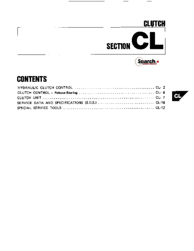
Image preview - the first page of the document
>> Download Clutch documenatation <<
Text preview - extract from the document
CLUTCH
SECTION CL
CONTENTS
HYDRAULIC CLUTCH CONTROL .......................................... CL- 2
CLUTCH CONTROL .Release Bearing ........................................ CL- 6
CLUTCH UNIT ........................................................... CL- 7
SERVICE DATA AND SPECIFICATIONS (S.D.S.) .............................. c1-10
SPECIAL SERVICE TOOLS . . . . . . . . . . . . . . . . . . . . . . . . . . . . . . . . . . . . . . . . . . . . . . . . CL-12
HYDRAULIC CLUTCH CONTROL
Push rod lock nut
(0.8-1.1.5.8-8.01
Clutch master cylinder
-
10.8 1.2,5.8.8.71
Operating cylinder
Operating cylinder
Clutch damper securing
fl : N m Ikg-m. ft-lbl
10.8. 1.1,5.8.8.01
SCL161
Precautions
0 Recommendedfluid i s brake fluid "DOT 3".
Do not reuse drained brake fluid.
0 Be careful not to splash brake fluid on painted
areas.
When removing and installing clutch tube, use
Tool GG94310000.
0 To clean or wash all parts of master cylinder,
operating cylinder and clutch damper, clean
brake fluid mu& be used.
0 Never use mineral oils such as gasoline or
kerosene. It will ruin the rubber parts of the
hydraulic system.
CL-2
HYDRAULIC CLUTCH CONTROL
Bleeding Procedure Adjusting Clutch Pedal
Carefully monitor fluid level a t master cylinder
during bleeding operation.
or clutch switch
Bleed air according to the following procedure.
Clutch damper + Operating cylinder
1. Top up reservoir with recommended brake
fluid. pedal n o p p r
2. Connect a transparent vinyl tube to air bleeder (0.8. 1.1,
valve. 5.8.8.0)
.Clutch -itch
Clutch dampet 12.15
Dash insulator
Dash floor p a n e l l
(9) : N m im,ft-lbl
SCL204
SCL162
Operating cylinder
Pedal height "H"
-
195 205 mm (7.68 8.07 in)
~
Pedal free play "A"
1 - 3 mm (0.04 - 0.12 in)
1. Adjust pedal height with pedal stopper or
clutch switch.
2. Adjust pedal free play with push rod.
3. Fully depress clutch pedal several times.
4. With clutch pedal depressed, open bleeder valve
to release air.
5. Close bleeder valve.
6. Repeat steps 3 through 5 above until brake
fluid comes out of air bleeder valve without air
bubbles.
CL-3
HYDRAULIC CLUTCH CONTROL
Adjusting Clutch Pedal (Cont'd)
I
3. Adjust clearance "C" between pedal stopper
rubber and threaded end of clutch interlock
switch while depressing clutch pedal fully.
Clearance C:
flAcp Pedal stopper rubber
I! \ 1 Clutch intsrlock w i t c h
Clutch Master Cylinder
'Piston assembly
Reservoir cap
Return spring
7 7
Reservoir
Reservoir band
Winder
(91
- ....-
Supply valve stopper
(91 2.5.3.9
(0.25-0.40.1.8-2.91
Remove this stopper,
when removing piston,
-
L M a r t e r cylinder securing nut
spring seat and return
(91 8 - 1 2 * Always replace when dissembled.
10.8- 12.5.8-8.71 (91: N.m I k g m , ft-lb1
spring. SCL163
INSPECTION
Check parts for wear or damage. Replace com-
ponent if any wear or damage is found.
CL-4
HYDRAULIC CLUTCH CONTROL
Operating Cylinder Clutch Damper
Bleeder screw
-
p 7 .10.7 0.9,5.1
9 .8.51
Gasket
Damper cover-,
Operating Cylinder7
-
13.1 4.1,
cylinder '% pl 3.7-6.0-'
\
Lm 8 - 11 (0.8. 1.1, 5.8-8.01
Piston spring (018.0!L ., ~
6 1
Piston 2.7.3.71
Piston cup : N m Ikgm. ft-lbl m: N m Ikgm,ft-lbl
SCLl64 SCL205
Do not reuse piston cup and dust cover. 0 Do not reuse piston cup.
0 Do not let oil touch the damper rubber as it
will ruin the rubber.
CL-5
CLUTCH CONTROL - Release Bearing
Release Bearing
REMOVAL AND INSTALLATION LUBRICATION
Apply recommended grease to contact surface
and sliding surface.
Too much lubricant might cause clutch disc facing
damage.
CL145 Pack this recess
Pres
SCL167
SCL166
CL-6
CLUTCH UNIT
Clutch Unit
*1: Slight burn or discoloration of contact surface
with clutch disc can be corrected by polishing
with emery paper.
main drive shaft doer not adhere t o clutch disc.
\
Clutch cover sscuring bolt
Clutch eaver'l
SCLZOS
WARNING:
Clean away clutch disc dust using a dust collector
after cleaning with a cloth. Do not use compressed
air.
CL- 7
CLUTCH UNIT
Inspecting Clutch Disc Inspecting Clutch Cover
Check clutch disc for runout, etc. Check height and unevenness of diaphragm
spring after setting Tool.
Diaphragm spring height "A":
Runout limit of facing
1st 115 mm (4.53 in1 from the hub center1 :
-
C240S: 37.5 - 39.5 mm (1.476 1.555 in)
1.0 mm 10.039 i n ) C250S: 36.5 - 38.5 mm (1.437. 1.516 in)
Uneven limit: 0.5 mm (0.020 in)
Maximum backlash of @ine//// o[;/laT
(at outer d g e of d i d : I
1.0 mm (0.039 in)
A
u or grease
SCL153
T- 1 -
yA/-
ST20050100
1
ST20050010
1
/'A
- 1
SCL155
Check clutch disc for wear.
Adjust unevenness of diaphragm spring with
Tool.
Measure the depth of rivet head
Mora than 0.3 mm (0.012 in1 SCL207
Check thrust rings for wear or damage by
shaking cover assembly up and down t o listen
for chattering noise, or lightly hammering on
rivets for a slightly cracked noise.
CL-8
CLUTCH UNIT
installing Clutch Cover
Insert Tool into clutch disc hub when installing
clutch cover and disc.
SCL2oa
CL-9
SERVICE DATA AND SPECIFICATIONS (S.D.S.)
General Specifications -Inspection and Adjustment
CLUTCH CONTROL SYSTEM CLUTCH PEDAL
Unit: mm (in1
Type of clutch Control Hydraulic
Pedal height "H" 195-205 17.688-8.071
CLUTCH MASTER CYLINDER Pedal free play "A" -
1 3 (0.04.0.121
Clearance between pedal
Inner diameter mm (in1 15.87 15/81
stopper rubber and threaded 1.5 - 3.5 10.059 - 0.1 381
end of clutch interlock w i t c h
CLUTCH OPERATING CYLINDER
CLUTCH DISC
Unit: mm l i n l
Model I 240TBL I 25OT8L
Model
Ensine I
240T8L
VG30E I
250T8L
VG30El
Wear limit o f facing surface
t o rivet head I 0.3 10.0121
Facing size
Runout limit
_____
I 1.0 (0.0391
Outer dia. x inner dia. x
thickness mm (in1
Distance of runout checkpoint
(from the hub center) I 115 (4.53)
I 120 (4.72)
Thickness of disc assembly
With load 5.884 N
II ._.,
--."
70~111
(0.311 -0.327)
Maximum backlash of spline
la1 outer edae of d i r l
_____
I 1.0 10.0391
(600kg, 1,323 I b l mm (in)
CLUTCH COVER
Unit: mm (in)
Model C240S C250S
Model I C240S I C250S
Diaphragm spring height
I 37.5. 39.5
I 36.5. 38.5
-
(1.476. 1.5551 (1.437 1.51 61
Full load
I 4,904
Ikg'Ibl (500. 1,1031 Uneven limit of diaphragm
spring toe height I 0.5 (0.020)
CL-10
SERVICE DATA AND SPECIFICATIONS (S.D.S.)
Tightening Torque
Unit N.m kg-m ft-lb
Pedal stopper lock nut 8.11 0.8-1.1 58-8.0
Clutch switch lock nut -
12 15 1.2-1.5 9-11
Fulcrum pin securing nut 16-22 1.6-2.2 12-16
Master cvlinder push rod 8-12 0.8 - 1.2 -
5.8 8.7
lock nut
Master cylinder 8-12 0.8-1.2 5.6-8.7
securing nut
Supply valve stopper 1.5-2.9 0.15-0.30 1.1 -2.2
Operating cylinder 30-40 3.1 -4.1 22-30
securing bolt
Bleeder screw 7 -9 0.7 - 0.9 5.1 .6.5
Clutch damper securing 8-11 0.8-1.1 58-8.0
bolt
Damper COYBI t o 3.7 -5.0 0.38 -0.51 -
2.7 3.7
cylinder
Clutch tube flare nut 15.16 1.5-18 11-13
Clutch hose to operating 17 - 2 0 1.7-2.0 12-14
cylinder and clutch
damper securing nut
Clutch mwr securing bolt
VG30E 22-29 2.2-3.0 16-22
VG30ET 34-44 3.5 - 4.5 25 .33
CL-11
SPECIAL SERVICE TOOLS
Tool number
Tool name
(Kent-Moore No.)
I
ST20600000 Clutch aligning bar
(J26366)
ST20050100 Distance piece
a
( - )
. :: ..
;
..
. .., . .
.... ;y
ST20050240 Diaphragm spring adjusting wrench
I - )
GGW310000
( - ) I Flare nut torque wrench
CL-12
◦ Jabse Service Manual Search 2026 ◦ Jabse Pravopis ◦ onTap.bg ◦ Other service manual resources online : Fixya ◦ eServiceinfo