Service Manuals, User Guides, Schematic Diagrams or docs for : . Car Manuals Nissan 300ZX 1984-1985,1988,1990,1994-1996 Approved 1988 Lubrication & Cooling
<< Back | HomeMost service manuals and schematics are PDF files, so You will need Adobre Acrobat Reader to view : Acrobat Download Some of the files are DjVu format. Readers and resources available here : DjVu Resources
For the compressed files, most common are zip and rar. Please, extract files with Your favorite compression software ( WinZip, WinRAR ... ) before viewing. If a document has multiple parts, You should download all, before extracting.
Good luck. Repair on Your own risk. Make sure You know what You are doing.
Image preview - the first page of the document
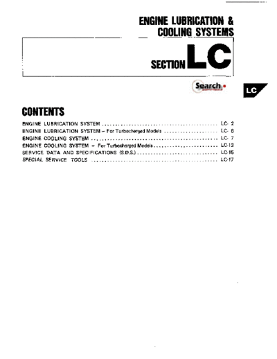
>> Download Lubrication & Cooling documenatation <<
Text preview - extract from the document
ENGINE LUBRICATION &
I COOLING SYSTEMS
SECTION LC
CONTENTS
ENGINE LUBRICATION SYSTEM ........................................... LC- 2
ENGINE LUBRICATION SYSTEM - For Turbocharged Models .................... LC- 6
ENGINE COOLING SYSTEM ............................................... LC- 7
ENGINE COOLING SYSTEM -
For Tuhocharged Models.. ...................... LC-13
SERVICE DATA AND SPECIFICATIONS (S.D.S.) .............................. LC-15
SPECIAL SERVICE TOOLS ............................................... LC-17
ENGINE LUBRICATION SYSTEM
Lubrication Circuit
'1: Additional lubrication circuit for turbocharged model
Oil passage '2 Additional oil cooler for turbo A I T model
SLC729
LC-2
ENGINE LUBRICATION SYSTEM
WARNING: If difference is extreme, check oil passage and oil
Be careful not t o burn yourself, as the engine pump for oil leaks.
and oil may be hot.
0 Oil pressure check should be done in "Neutral"
gear position.
1. Check oil level.
2. Remove oil pressure switch.
5. Install oil pressure switch.
Use proper liquid sealant.
0 : 13 17 N m (1.3 - 1.7 kgm, 9 - 12 ftJb)
~
SLCS45
3. '! II pressure gauge.
4. Start engine and warm it up t o normal operat-
ing temperature and, then check oil pressure
with engine running under no-load.
Engine Approximate discharge
prewre kPs IksJm'. psi)
Idle speed More than 59 (0.6.9)
-
Non.turbo 363 451 13.7.4.6,53.65)
-
Turbo 373.432 (3.8 4.4.54.63)
LC-3
ENGINE LUBRICATION SYSTEM
Oil Pump Disassembly and Assembly
1. Drain oil.
2. Remove oil pan.
In case of on-vehicle service, refer to Oil Pan
for removal in section EM.
3. Remove oil pump assembly.
When installing oil pump, apply engine oil to inner
and outer gear.
Be sure that O-ring is properly fitted on.
-
112 1.6,
9.121 (9) : N m (kgm, ft-lb)
SLC936
- Cover
r*. 4 . 5 (0.4 .0.5,2.9.3.6)
.~
Oil pump body ~
(9) 6.3 .8.3
10.64 - 0.85.4.6 - 6.1 I
(9) : N m Ikg-m. ft-lbl SLC759
LC-4
ENGINE LUBRICATION SYSTEM
Oil Pump Inspection
1. Visually inspect components for wear and If excessive wear is found, replace gear set or entire
damage. oil pump assembly.
2. Check oil pressure regulator valve sliding sur-
face and valve spring. Standard clearance: Unit: mm (in)
If damaged, replace as a valve set. Body t o outer gear
clearance 0
I -
0.1 1 - 0.20(0.0043 0.0079)
Spring 7
Regulator
WlW
/-lI/
7 I \\
to inner gear
clearance
I 0.05.0.09 (0.0020 0.0035)
-
Housing to Outer gear
0.05- 0.11 (0.0020 0.0043)
-
SLC295
clearance 0
3. Using a feeler gauge, check the following clear-
ance.
Oil Pressure Relief Valve
Inspection
Inspect for smooth operation by pushing ball.
-
u SLC549
A
SLCS51
Replace as a valve assembly, when replacing.
LC-5
ENGINE LUBRICATION SYSTEM
- For Turbocharged Models
Removal and Installation
OIL DELIVERY SYSTEM
After installation, run engine for a few minutes and check for leaks.
16-24
n 15-20
Washer oyTI:
1 . - 2.0,ll - 14)
15
0
13-16
(1.3.1.6.9-12)
n : N m (kgm. ft-lb)
SLC058A
ENGINE OIL COOLER (A/T models)
Be careful not to burn yourself as engine oil is hot.
After installation, run engine for a few minutes and check for oil leaks.
~ ( 9 59 - 74 (6.0 - 74.43 -64)
1
Oil filter
bracket
7 8-1110.8-1.1.6.8-8.0)
, 4 .r - .
A
, " .
I.D. -
u o*,
0
"S
- Washer
L Oil mder
- Oil filter rud
-T
[91 14-18'-
11.4-1.8,
10.13)
59 - 74 18.0.7.5,43 - 64)
SLC984
LC-6
ENGINE COOLING SYSTEM
Cooling Circuit
To avoid danger of being scalded, never attempt t o drain coolant when engine is hot.
If it is necessary t o remove radiator cap when radiator i s hot, turn cap slowly counterclockwise t o the first
stop. After all pressure in the cooling system is released, turn cap past the stop and remove it.
Always replaca with new gasket and O-ring.
Refer to MA section for changing engine coolant.
Radiator cap Reservoir tank
Thermostat: Open
Radiator
4
Thermostat
Water outlet
housing
- Thermostat: Closed
4
Thermostat
housing Throttle chamber Turbocharger Air regulator
4
Heater
*Turbocharged models Only +
Intake manifold
Water pump (Water parlagel
I A
SLC728
LC-7
ENGINE COOLING SYSTEM
Checking Cooling System
WARNING: CHECKING RADIATOR CAP
Never remove the radiator cap when the engine is Apply pressure to radiator cap by means of a cap
hot; serious burns could be caused by high pressure tester to see if it is satisfactory.
fluid escaping from the radiator.
Wrap a thick cloth around cap and carefully re- Radiator cap relief pressure:
move the cap by turning it a quarter turn t o allow
- -
78 - 98 kPa (0.8 1.0 kg/cm2, 11 14 psi)
built-up pressure t o escape and then turn the cap
all the way off.
CHECKING COOLING SYSTEM HOSES
Check hoses for proper attachment, leaks, cracks,
damage, loose connections, chafing and deteriora-
tion.
CHECKING COOLING SYSTEM FOR LEAKS \ SLC613
Apply pressure to the cooling system by means of
a tester t o check for leakage.
Testing pressure:
157 kPa (1.6 kg/cm2, 23 psi)
SLC612
LC-8
ENGINE COOLING SYSTEM
Water Pump Removal and Installation (On-vehicle service)
Water pump can not be disassembled and should be
replaced as a unit
To avoid deforming timing cover, make sure there is
adequate clearance between cover and h o a clamp.
After installingwater pump, connect hosa and clamp
sacurely, then check for leaks using cap tester.
SLC838
Water Pump Inspection
Drain coolant from drain plugs on both sides of
cylinder block, and radiator. Check for excessive end play and rough operation.
SLC815
SLC738
CAUTION:
When removing water pump assembly, be careful
not to get coolant on timing belt.
LC-9
ENGINE COOLING SYSTEM
Thermostat Description (Bottom by-pass coolant flow)
water omlet
Coolant flow om
Thermostat
through water outlet
Own A little
+ ClOS Much
SLC566
Thermostat Removal and Installation
CAUTION:
Drain coolant from drain cocks on cylinder block side and radiator.
Remove radiator shroud, cooling fan and water suction pipe securing bolt, then remove thermostat.
After installation, run engine for a few minutes, and check for leaks.
.-.
L m 1 6 - 2 1 Nmll.6.2.1 kpm.12-15ft-lbI
SLC939
LC-10
ENGINE COOLING SYSTEM
Thermosta
1. Check for valve seating condition a t ordinary
temperatures. It should seat tightly.
2. Check valve opening temperature and maxi-
mum valve lift.
I Standard
Valve opening temperature
'C ( O F )
I 76.5 (170)
Maximum valve lift
'
mmf'C (in/'F)
I 10/90 (0.39/194)
SLC343
3. Then check if valve closes a t 5◦ Jabse Service Manual Search 2026 ◦ Jabse Pravopis ◦ onTap.bg ◦ Other service manual resources online : Fixya ◦ eServiceinfo