Service Manuals, User Guides, Schematic Diagrams or docs for : . Car Manuals Nissan Murano 2003-2007.2009 Approved Nissan Murano 2006 fax
<< Back | HomeMost service manuals and schematics are PDF files, so You will need Adobre Acrobat Reader to view : Acrobat Download Some of the files are DjVu format. Readers and resources available here : DjVu Resources
For the compressed files, most common are zip and rar. Please, extract files with Your favorite compression software ( WinZip, WinRAR ... ) before viewing. If a document has multiple parts, You should download all, before extracting.
Good luck. Repair on Your own risk. Make sure You know what You are doing.
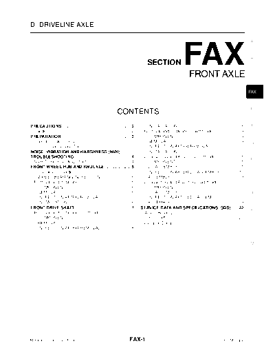
Image preview - the first page of the document

>> Download fax documenatation <<
Text preview - extract from the document
FRONT AXLE


D DRIVELINE/AXLE

                                                                                                                                                                  A


                                                                                      SECTION                    FAX  FRONT AXLE
                                                                                                                                                                  B


                                                                                                                                                                  C


                                                                                                                                                                  FAX


                                                                                                                                                                  E
                                                                  CONTENTS
PRECAUTIONS ......................................................... 2 .            INSTALLATION .................................................... 8 .        F
 Caution .................................................................... 2
                                                                        .          Removal and Installation (Right Side) ..................... 9         .
PREPARATION .......................................................... 3.            COMPONENTS .................................................... 9   .
 Special Service Tools (SST) .................................... 3     .            REMOVAL ............................................................ 9
                                                                                                                                                         .        G
 Commercial Service Tools ....................................... 3     .            INSPECTION AFTER REMOVAL ...................... 10                  .
NOISE, VIBRATION AND HARSHNESS (NVH)                                                 INSTALLATION .................................................. 10  .
TROUBLESHOOTING ............................................... 4       .          Disassembly and Assembly (Left Side) ................. 11             .
                                                                                                                                                                  H
 NVH Troubleshooting Chart .................................... 4       .            COMPONENTS .................................................. 11    .
FRONT WHEEL HUB AND KNUCKLE ..................... 5                     .            DISASSEMBLY .................................................. 11   .
 On-Vehicle Inspection ............................................. 5  .            INSPECTION AFTER DISASSEMBLY ............... 12                     .
   WHEEL BEARING INSPECTION ........................ 5                  .            ASSEMBLY ........................................................ 13.         I
 Removal and Installation ......................................... 5   .          Disassembly and Assembly (Right Side) ............... 16              .
   COMPONENTS ................................................... 5     .            COMPONENTS .................................................. 16    .
   REMOVAL ............................................................ 5
                                                                        .            DISASSEMBLY .................................................. 16   .         J
   INSPECTION AFTER REMOVAL ........................ 6                  .            INSPECTION AFTER DISASSEMBLY ............... 18                     .
   INSTALLATION .................................................... 6  .            ASSEMBLY ........................................................ 19.
FRONT DRIVE SHAFT .............................................. 7      .         SERVICE DATA AND SPECIFICATIONS (SDS) ..... 22                         .
                                                                                                                                                                  K
 Removal and Installation (Left Side) ....................... 7         .          Wheel Bearing ....................................................... 22
                                                                                                                                                         .
   COMPONENTS ................................................... 7     .          Drive Shaft ............................................................. 22
                                                                                                                                                         .
   REMOVAL ............................................................ 7
                                                                        .          Dynamic Damper ................................................... 22 .
   INSPECTION AFTER REMOVAL ........................ 8                  .                                                                                          L


                                                                                                                                                                  M


Revision: 2005 September                                                   FAX-1                                                            2006 Murano
                                           PRECAUTIONS

PRECAUTIONS                                                                                       PFP:00001

Caution                                                                                              NDS0008P


Observe the following precautions when disassembling and servicing drive shaft.
q  Perform work in a location which is as dust-free as possible.
q  Before disassembling and servicing, clean the outside of parts.
q  Prevention of the entry of foreign objects must be taken into account during disassembly of the service
   location.
q  Disassembled parts must be carefully reassembled in the correct order. If work is interrupted, a clean
   cover must be placed over parts.
q  Paper shop cloths must be used. Fabric shop cloths must not be used because of the danger of lint adher-
   ing to parts.
q  Disassembled parts (except for rubber parts) should be cleaned with kerosene which shall be removed by
   blowing with air or wiping with paper shop cloths.


Revision: 2005 September                         FAX-2                                        2006 Murano
                                            PREPARATION

PREPARATION                                                                                                  PFP:00002
                                                                                                                           A
Special Service Tools (SST)                                                                                     NDS0008Q


The actual shapes of Kent-Moore tools may differ from those of special service tools illustrated here.
    Tool number
                                                                                                                           B
    (Kent-Moore No.)                                                   Description
    Tool name
                                                                                                                           C
    HT72520000
    (J-25730-A)
    Ball joint remover
                                                                       Removing steering outer socket                      FAX
     a: 33 mm (1.30 in)
     b: 50 mm (1.97 in)
     r: 11.5 mm (0.453 in)
                                                           NT546
                                                                                                                           E


    KV40107500                                                                                                             F
    (
◦ Jabse Service Manual Search 2024 ◦ Jabse Pravopis ◦ onTap.bg ◦ Other service manual resources online : Fixya ◦ eServiceinfo