Service Manuals, User Guides, Schematic Diagrams or docs for : . Car Manuals Nissan Maxima 2000-2005 Approved Nissan Maxima 2000 mt

<< Back | Home

Most service manuals and schematics are PDF files, so You will need Adobre Acrobat Reader to view : Acrobat Download Some of the files are DjVu format. Readers and resources available here : DjVu Resources
For the compressed files, most common are zip and rar. Please, extract files with Your favorite compression software ( WinZip, WinRAR ... ) before viewing. If a document has multiple parts, You should download all, before extracting.
Good luck. Repair on Your own risk. Make sure You know what You are doing.


Image preview - the first page of the document
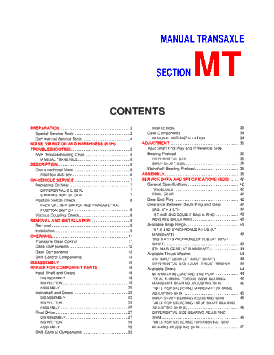
mt


>> Download mt documenatation <<

Text preview - extract from the document
                                                                                                    MANUAL TRANSAXLE


                                                                                                SECTION                        MT
                                                                CONTENTS
PREPARATION ...............................................................2               INSPECTION ...........................................................33
  Special Service Tools ..................................................2             Case Components .....................................................34
  Commercial Service Tools ...........................................4                    REMOVAL AND INSTALLATION ...............................34
NOISE, VIBRATION AND HARSHNESS (NVH)                                                  ADJUSTMENT ...............................................................35
TROUBLESHOOTING .....................................................5                  Input Shaft End Play and Differential Side
  NVH Troubleshooting Chart.........................................5                   Bearing Preload .........................................................35
    MANUAL TRANSAXLE ...............................................5                      DIFFERENTIAL SIDE ...............................................35
DESCRIPTION .................................................................6             INPUT SHAFT SIDE.................................................36
  Cross-sectional View ...................................................6             Mainshaft Bearing Preload ........................................36
    RS5F50A AND 50V ....................................................6             ASSEMBLY....................................................................38
ON-VEHICLE SERVICE ..................................................7                SERVICE DATA AND SPECIFICATIONS (SDS) .........42
  Replacing Oil Seal .......................................................7           General Specifications...............................................42
    DIFFERENTIAL OIL SEAL ..........................................7                      TRANSAXLE ...........................................................42
    STRIKING ROD OIL SEAL .........................................7                       FINAL GEAR ...........................................................42
  Position Switch Check .................................................8              Gear End Play ...........................................................42
        BACK-UP LAMP SWITCH AND PARK/NEUTRAL                                            Clearance Between Baulk Ring and Gear ................42
        POSITION SWITCH ...................................................8               3RD, 4TH & 5TH......................................................42
  Viscous Coupling Check..............................................8                    1ST AND 2ND DOUBLE BAULK RING ......................43
REMOVAL AND INSTALLATION ...................................9                              REVERSE BAULK RING ..........................................43
  Removal.......................................................................9       Available Snap Rings ................................................43
  Installation....................................................................9          1ST & 2ND SYNCHRONIZER HUB (AT
                                                                                             MAINSHAFT) ...........................................................43
OVERHAUL ...................................................................11
                                                                                             3RD & 4TH SYNCHRONIZER HUB (AT INPUT
  Transaxle Gear Control .............................................11
                                                                                             SHAFT) ...................................................................43
  Case Components .....................................................12
                                                                                             5TH MAIN GEAR (AT MAINSHAFT) ..........................44
  Gear Components .....................................................13                Available Thrust Washer............................................44
  Shift Control Components .........................................14                     4TH INPUT GEAR (AT INPUT SHAFT) ......................44
DISASSEMBLY..............................................................15                DIFFERENTIAL SIDE GEAR THRUST WASHER ........44
REPAIR FOR COMPONENT PARTS ...........................18                                 Available Shims .........................................................44
  Input Shaft and Gears ...............................................18                  BEARING PRELOAD AND END PLAY ......................44
     DISASSEMBLY ........................................................18                TOTAL TURNING TORQUE (NEW BEARING) ............45
     INSPECTION ...........................................................19              MAINSHAFT BEARING ADJUSTING SHIM ................45
     ASSEMBLY .............................................................20                TABLE FOR SELECTING MAINSHAFT BEARING
  Mainshaft and Gears .................................................23                    ADJUSTING SHIM ...................................................45
     DISASSEMBLY ........................................................23                  INPUT SHAFT BEARING ADJUSTING SHIM .............46
     INSPECTION ...........................................................24                TABLE FOR SELECTING INPUT SHAFT BEARING
     ASSEMBLY .............................................................26                ADJUSTING SHIM(S) ...............................................46
  Final Drive..................................................................27            DIFFERENTIAL SIDE BEARING ADJUSTING
     DISASSEMBLY ........................................................27                  SHIM ......................................................................46
     INSPECTION ...........................................................29                TABLE FOR SELECTING DIFFERENTIAL SIDE
     ASSEMBLY .............................................................29                BEARING ADJUSTING SHIM ....................................47
  Shift Control Components .........................................33
                                           PREPARATION
Special Service Tools

                                           Special Service Tools                                           NFMT0001


 Tool number
                             Description
 Tool name

 KV38105210                                                Measuring turning torque of final drive assembly
 Preload adapter                                           Measuring total turning torque


                             NT075

 KV32101000                                                Removing and installing retaining pin
 Pin punch                                                 a: 4 mm (0.16 in) dia.


                             NT410

 ST22730000                                                Removing mainshaft front and rear bearing inner
 Puller                                                    race
                                                           a: 82 mm (3.23 in) dia.
                                                           b: 30 mm (1.18 in) dia.


                             NT411

 ST30031000                                                Removing input shaft front and rear bearing
 Puller                                                    Removing 4th & 5th main gear
                                                           a: 90 mm (3.54 in) dia.
                                                           b: 50 mm (1.97 in) dia.


                             NT411

 ST30021000                                                Removing 5th synchronizer
 Puller                                                    Removing 3rd & 4th synchronizer
                                                           Removing 2nd & 3rd main gear
                                                           a: 110 mm (4.33 in) dia.
                                                           b: 68 mm (2.68 in) dia.


                             NT411

 ST3306S001                                                Removing differential side bearing inner race
 Differential side bearing                                 a: 38 mm (1.50 in) dia.
 puller set                                                b: 28.5 mm (1.122 in) dia.
 1: ST33051001                                             c: 130 mm (5.12 in)
 Puller                                                    d: 135 mm (5.31 in)
 2: ST33061000                                             e: 100 mm (3.94 in)
 Adapter


                             NT675

 ST33290001                                                Removing differential oil seal
 Puller                                                    Removing mainshaft rear bearing outer race
                                                           Removing differential side bearing outer race
                                                           a: 250 mm (9.84 in)
                                                           b: 160 mm (6.30 in)


                             NT414


                                                MT-2
                                    PREPARATION
                                                                        Special Service Tools (Cont'd)

Tool number
                      Description
Tool name

ST33400001                                        Installing differential oil seal (50A and 50V right
Drift                                             side)
                                                  a: 60 mm (2.36 in) dia.
                                                  b: 47 mm (1.85 in) dia.


                      NT086

ST30600000                                        Installing input shaft front bearing
Drift                                             a: 36 mm (1.42 in) dia.
                                                  b: 31 mm (1.22 in) dia.


                      NT065

ST22452000                                        Installing 3rd, 4th and 5th main gear
Drift                                             a: 45 mm (1.77 in) dia.
                                                  b: 36 mm (1.42 in) dia.


                      NT065

ST30621000                                        Installing mainshaft rear bearing outer race
Drift                                             (Use with ST30611000.)
                                                  a: 79 mm (3.11 in) dia.
                                                  b: 59 mm (2.32 in) dia.


                      NT073

ST30611000                                        (Use with ST30621000.)
                                                  a: 15 mm (0.59 in)
                                                  b: 335 mm (13.19 in)
                                                  c: 25 mm (0.98 in) dia.
                                                  d: M12 x 1.5P


                      NT419

KV38106500                                        Measuring side gear clearance
Preload adapter


                      NT087

KV38100300                                        Installing differential side bearing
(     --          )                               a: 54 mm (2.13 in) dia.
Drift                                             b: 46 mm (1.81 in) dia.
                                                  c: 32 mm (1.26 in) dia.


                      NT085

ST30613000                                        Installing differential side bearing
(     --          )                               a: 72 mm (2.83 in) dia.
Drift                                             b: 48 mm (1.89 in) dia.


                      NT073


                                       MT-3
                                         PREPARATION
Commercial Service Tools

                                         Commercial Service Tools                                          NFMT0002


 Tool name                 Description

 Drift                                                  Installing differential side bearing inner race
                                                        a: 45 mm (1.77 in) dia.
                                                        b: 41 mm (1.61 in) dia.


                           NT065

 Drift                                                  Installing differential side bearing outer race
                                                        a: 69 mm (2.72 in) dia.
                                                        b: 64 mm (2.52 in) dia.


                           NT065

 Drift                                                  Installing striking rod oil seal
                                                        a: 38 mm (1.50 in) dia.
                                                        b: 20 mm (0.79 in) dia.


                           NT065

 Drift                                                  Installing differential oil seal (50V left side)
                                                        a: 92 mm (3.62 in) dia.
                                                        b: 72 mm (2.83 in) dia.


                           NT065

 Drift                                                  Installing differential side bearing outer race (50V)
                                                        a: 99 mm (3.90 in) dia.
                                                        b: 94 mm (3.70 in) dia.


                           NT065


                                              MT-4
                                                                                                                                                                                                                                                                                                                                                                                                                       NFMT0003

        NOISE, VIBRATION AND HARSHNESS (NVH) TROUBLESHOOTING
                                                                                                                                                                                                                                                                                                                               NVH

                                                                          NVH Troubleshooting Chart                                                                                                                                                                                                                                                                                                                  NFMT0003S01
Use the chart below to help you find the cause of the symptom. The numbers indicate the order of the inspec-
tion. If necessary, repair or replace these parts.
MANUAL TRANSAXLE                                                                                                                                                                                                                                                                                                                                                                                     NFMT0003S0101


                                                                            Refer to MA-25, "Checking M/T Oil".


                                                                                                                                         MT-12

                                                                                                                                                            MT-12

                                                                                                                                                                                         MT-12


                                                                                                                                                                                                                                               MT-14

                                                                                                                                                                                                                                                                                                           MT-14

                                                                                                                                                                                                                                                                                                                                 MT-13

                                                                                                                                                                                                                                                                                                                                                          MT-13

                                                                                                                                                                                                                                                                                                                                                                                      MT-13

                                                                                                                                                                                                                                                                                                                                                                                                                         MT-13
                                                                                                                                                                                                                    MT-11
 Reference page


                                                                                                                                                                                                                                               CHECK PLUG RETURN SPRING AND CHECK BALL (Worn or damaged)

 SUSPECTED PARTS
 (Possible cause)


                                                                                                                                                                                                                                                                                                                                                                                      BAULK RING (Worn or damaged)
                                                                                                                                                                                                                    SHIFT CONTROL ROD (Worn)


                                                                                                                                                                                                                                                                                                                                                          BEARING (Worn or damaged)
                                                                                                                                                            OIL SEAL (Worn or damaged)


                                                                                                                                                                                                                                                                                                                                                                                                                         INSERT SPRING (Damaged)
                                                                                                                                                                                         O-RING (Worn or damaged)


                                                                                                                                                                                                                                                                                                                                 GEAR (Worn or damaged)
                                                                                                                                         GASKET (Damaged)


                                                                                                                                                                                                                                                                                                           SHIFT FORK (Worn)
                                                                                                                  (Oil level is high.)
                                                    (Oil level is low.)

                                                                            (Wrong oil)


                  Noise                               1                         2                                                                                                                                                                                                                                                  3                        3

                  Oil leakage                                                   3                                   1                     2                   2                            2
 Symptoms
                  Hard to shift or will not shift                               1                                   1                                                                                                 2                                                                                                                                                                  3                                 3

                  Jumps out of gear                                                                                                                                                                                   1                              2                                                      3                      3


                                                                                                                  MT-5
                                                  NFMT0004

                        DESCRIPTION
Cross-sectional View

                       Cross-sectional View    NFMT0004S01
RS5F50A AND 50V                               NFMT0004S0101


                                               SMT873D


                            MT-6
      ON-VEHICLE SERVICE
                                                             Replacing Oil Seal

           Replacing Oil Seal                                           NFMT0005
           DIFFERENTIAL OIL SEAL                                      NFMT0005S01
           1.   Drain gear oil from transaxle.
           2.   Remove drive shafts. Refer to AX-9, "Drive Shaft".
           3.   Remove differential oil seals.


SMT563AA

           4.   Install differential oil seals.
           +    Apply multi-purpose grease to seal lip of oil seal before
                installing.
           5.   Install drive shafts. Refer to AX-9, "Drive Shaft".


SMT564AA

           +    Install oil seals so that dimension "A" is within specifica-
                tions.
                   Dimension "A":
                      -0.5 mm (-0.020 in) to 0.5 mm (0.020 in)


SAT489JB

           STRIKING ROD OIL SEAL                                      NFMT0005S02
           1.   Remove transaxle control rod from yoke.
           2.   Remove retaining pin.
           +    Be careful not to damage boot.


SMT565AA

           3.   Remove striking rod oil seal.


 SMT566A


                    MT-7
                                   ON-VEHICLE SERVICE
Replacing Oil Seal (Cont'd)
                                        4.   Install striking rod oil seal.
                                        +    Apply multi-purpose grease to seal lip of oil seal before
                                             installing.


                              SMT570A

                                        +    Drive it in as far as it will go.


                              SMT876D

                                        Position Switch Check                                          NFMT0006
                                        BACK-UP LAMP SWITCH AND PARK/NEUTRAL
                                        POSITION SWITCH                                              NFMT0006S01
                                        +    Check continuity.
                                                    Gear position                      Continuity

                                        Reverse                                          1-5

                                        Neutral                                          2-6

                                        Except reverse and neutral                        No
                              SMT872D

                                        Viscous Coupling Check                                         NFMT0030
                                        1.    Apply parking brake firmly and place shift lever in the neutral
                                              position.
                                        2. Jack up front wheels.
                                        3. Rotate one front wheel and check turning direction of the other
                                              front wheel.
                                        Turning direction of the two wheels is opposite:
                                        The viscous coupling is not functioning normally.
                                        Turning direction of the two wheels is the same:
                                        If differential side gear and pinion mate gear thrust washers are
                                        OK, viscous coupling is functioning normally.


                              SMT108C


                                                  MT-8
                                                                     NFMT0008

REMOVAL AND INSTALLATION
                                                                   Removal

          Removal                                                  NFMT0008S01
          CAUTION:
          Remove the crankshaft position sensor (POS) from transaxle
          assembly before separating transaxle from engine.
          Be careful not to damage sensor edge.
          1. Remove battery and its bracket.
          2. Remove air cleaner box with mass air flow sensor.


SMT109C

          3.   Remove clutch operating cylinder from transaxle.
          4.   Remove clutch hose clamp.
          5.   Disconnect speedometer pinion, PNP switch and ground har-
               ness connectors.
          6.   Remove starter motor from transaxle.
          7.   Remove crankshaft position sensor (POS) from transaxle front
               side.


SMT650C

          8.  Remove shift control rod and support rod bracket from tran-
              saxle.
          9. Drain gear oil from transaxle.
          10. Draw out drive shafts from transaxle. Refer to AX-9, "Drive
              Shaft".
          11. Support engine of transaxle by placing a jack under oil pan.
          CAUTION:
          Do not place jack under oil pan drain plug.
          12. Remove bolts securing center member.

SMT651C

          13. Remove LH mount.
          14. Remove bolts securing transaxle.
          15. Lower transaxle while supporting it with a jack.


SMT652C

          Installation                                             NFMT0008S02
          +    Tighten LH mount and center member bolts. Refer to EM-58,
               "Installation".
          +    Tighten clutch operating cylinder bolts. Refer to CL-5,
               "CLUTCH SYSTEM".
          +    Install drive shafts. Refer to AX-9, "Drive Shaft".
          +    Tighten all transaxle bolts and any part removed.


                  MT-9
                        REMOVAL AND INSTALLATION
Installation (Cont'd)

                                   Bolt No.       Tightening torque    N


◦ Jabse Service Manual Search 2026 ◦ Jabse PravopisonTap.bg ◦ Other service manual resources online : FixyaeServiceinfo