Service Manuals, User Guides, Schematic Diagrams or docs for : . Car Manuals Nissan Micra 2003-2006 Approved sma ATC-002
<< Back | HomeMost service manuals and schematics are PDF files, so You will need Adobre Acrobat Reader to view : Acrobat Download Some of the files are DjVu format. Readers and resources available here : DjVu Resources
For the compressed files, most common are zip and rar. Please, extract files with Your favorite compression software ( WinZip, WinRAR ... ) before viewing. If a document has multiple parts, You should download all, before extracting.
Good luck. Repair on Your own risk. Make sure You know what You are doing.
Image preview - the first page of the document
>> Download ATC-002 documenatation <<
Text preview - extract from the document
                         TROUBLE DIAGNOSIS
TROUBLE DIAGNOSIS
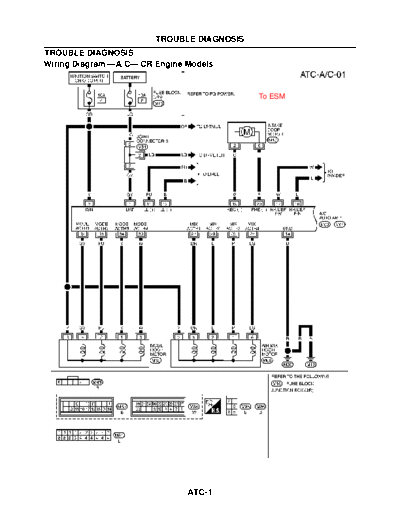
Wiring Diagram --A/C-- CR Engine Models


                                             To ESM


                                                      MJWA0061E


                                 ATC-1
TROUBLE DIAGNOSIS


                    MJWA0110E


      ATC-2
TROUBLE DIAGNOSIS


                    MJWA0111E


      ATC-3
TROUBLE DIAGNOSIS


                    MJWA0064E


      ATC-4
                         TROUBLE DIAGNOSIS
Wiring Diagram --A/C-- K9K Engine Models


                                             To ESM


                                                      MJWA0036E


                                 ATC-5
TROUBLE DIAGNOSIS


                    MJWA0112E


      ATC-6
TROUBLE DIAGNOSIS


                    MJWA0113E


      ATC-7
TROUBLE DIAGNOSIS


                    MJWA0039E


      ATC-8
                                               TROUBLE DIAGNOSIS
Ambient Sensor System
                                                    To ESM
1. CHECK POWER SUPPLY CIRCUIT
Disconnect ambient sensor connector, turn ignition switch ON, and
check voltage between the terminal 1 and ground.
                 Connector terminal                 Voltage
      Ambient sensor
                                      Ground       Approx. 5V
            1
OK or NG
 OK    >> GO TO 2.
 NG    >> GO TO 4.
                                                                        MJIB0116E


2. CHECK CIRCUIT CONTINUITY
1.   Disconnect the A/C auto amp. connector.
2.   Check continuity between ambient sensor terminal 2 and A/C
     auto amp. terminal 6.
                  Connector terminal               Continuity
      Ambient sensor             A/C auto amp.
                                                      Yes
             2                           6
Does continuity exist?
 YES >> GO TO 3.
 NO     >> Repair harness or connector.                                 MJIB0117E


3. CHECK AMBIENT SENSOR
Check resistance between terminals 1 and 2 on ambient sensor.
OK or NG
 OK     >> 1. Replace A/C auto amp.
             2. Perform self-diagnosis step 2. Make sure result is
                normal. Refer to ATC-33, "Self-Diagnosis Function"
                on ESM.
 NG       >> 1. Replace ambient sensor.
                2. Perform self-diagnosis step 2. Make sure result is
                   normal. Refer to ATC-33, "Self-Diagnosis Function"
                   on ESM.                                              MJIB0118E


                                                      ATC-9
                                              TROUBLE DIAGNOSIS

4. CHECK CIRCUIT CONTINUITY
1.   Disconnect the A/C auto amp. connector.
2.   Check continuity between ambient sensor terminal 1 and A/C
     auto amp. terminal 4.
                Connector terminal                   Continuity
      Ambient sensor           A/C auto amp.
                                                        Yes
            1                          4

3.   Check continuity between ambient sensor terminal 1 and
     ground.
                                                                                                       MJIB0119E
                Connector terminal                   Continuity
      Ambient sensor
                                     Ground            None
            1
OK or NG
 OK    >> 1. Replace A/C auto amp.
            2. Perform self-diagnosis step 2. Make sure result is normal. Refer to ATC-33, "Self-Diagnosis
               Function" on ESM.
 NG      >> Repair harness or connector.
Blower Motor System                                           To ESM
Symptom: Operation malfunction of blower motor
1. CHECK POWER SUPPLY CIRCUIT (BLOWER MOTOR)
Turn ignition switch ON, and check voltage between blower motor
terminal 2 and ground.
                Connector terminal                  Voltage
       Blower motor
                                     Ground      Battery voltage
            2

OK or NG
 OK    >> GO TO 2.
 NG    >> Check power supply circuit and 15A fuses [Nos. 9 and
          10, located in the fuse block (J/B)]. Refer to PG-4,                                       MJIB0120E
          "POWER SUPPLY ROUTING" on ESM.
          q If OK, check for open circuit in wiring harness. Repair or replace as necessary.

          q If NG, replace fuse and check wiring harness for short circuit. Repair or replace as necessary.


2. CHECK POWER SUPPLY CIRCUIT (A/C AUTO AMP.)
1.   Disconnect A/C auto amp. connector.
2.   Turn ignition switch ON, and check voltage between A/C auto
     amp. terminal 8 and ground.

                Connector terminal                  Voltage
      A/C auto amp.
                                     Ground      Battery voltage
            8
OK or NG
 OK    >> GO TO 3.
 NG    >> Repair harness or connector.
                                                                                                       MJIA0230E


                                                      ATC-10
                                                TROUBLE DIAGNOSIS

3. CHECK POWER SUPPLY CIRCUIT (FAN CONTROL AMP.)
1.   Disconnect the fan control amp. connector.
2.   Turn ignition switch ON, and check voltage between fan control
     amp. terminal 1, 5 and ground.

                 Connector terminal
                                                     Voltage
      Fan control amp.
             1                        Ground
                                                  Battery voltage
             5
OK or NG
 OK    >> GO TO 4.
                                                                      MJIA0100E
 NG    >> q Between terminal 1 and ground: Repair the harness
            or connector.
          q Between terminal 5 and ground: GO TO 7.


4. CHECK BLOWER MOTOR FEEDBACK SIGNAL
Turn ignition switch ON, and check voltage between A/C auto amp.
terminal 9 and ground.
                  Connector terminal                   Voltage
      A/C auto amp.
                                       Ground        Approx. 12V
            9
OK or NG
 OK    >> GO TO 5.
 NG    >> GO TO 9.
                                                                      MJIA0231E


5. CHECK GROUND CIRCUIT
Check continuity between fan control amp. terminal 2 and ground.
                  Connector terminal                  Continuity
     Fan control amp.
                                       Ground            Yes
            2
Does continuity exist?
 YES >> GO TO 6.
 NO     >> Repair harness or connector.

                                                                      MJIA0102E


                                                        ATC-11
                                             TROUBLE DIAGNOSIS

6. CHECK 1: FAN CONTROL AMP. CONTROL SIGNAL
Check waveform between fan control amp. terminal 3 and ground.


                                                                     MJIA0103E

OK or NG
 OK    >> Replace the fan control amp.
 NG    >> q Fan speed is stuck at speed 4: GO TO 11.
          q Fan speed is stuck at speed 1: GO TO 12.


7. CHECK BLOWER MOTOR
1.   Remove the blower motor.
2.   Check continuity between blower motor terminal 1 and terminal
     2.

                Connector terminal                Continuity
                     Blower motor
                                                     Yes
           1                          2
Does continuity exist?
 YES >> GO TO 8.
                                                                        MJIB0121E
 NO     >> Replace the blower motor.

8. CHECK CIRCUIT CONTINUITY
1.   Disconnect the blower motor and fan control amp. connectors.
2.   Check continuity between the blower motor terminal 1 and fan
     control amp. terminal 5.

                Connector terminal
                                                  Continuity
      Blower motor             Fan control amp.
           1                          5              Yes

Does continuity exist?
 YES >> End of trouble diagnosis
                                                                        MJIB0122E
 NO     >> Repair harness or connector.


                                                    ATC-12
                                                 TROUBLE DIAGNOSIS

9. CHECK CIRCUIT CONTINUITY
1.     Disconnect the fan control amp. and A/C auto amp. connectors.
2.     Check continuity between fan control amp. terminal 4 and A/C
       auto amp. terminal 9.

                     Connector terminal
                                                              Continuity
       Fan control amp.             A/C auto amp.
               4                          9                      Yes
Does continuity exist?
 YES >> GO TO 10.
                                                                                 MJIA0234E
 NO     >> Repair harness or connector.

10. CHECK FAN CONTROL AMP.
Check continuity between fan control amp. terminals 4 and 5.
                     Connector terminal
                                                              Continuity
                     Fan control amp.
               4                          5                      Yes
Does continuity exist?
 YES >> End of trouble diagnosis
 NO     >> Replace the fan control amp.

                                                                                 MJIA0235E


11. CHECK CIRCUIT CONTINUITY
1.     Disconnect the fan control amp. and A/C auto amp. connectors.
2.     Check continuity between fan control amp. terminal 3 and A/C
       auto amp. terminal 10.

                     Connector terminal
                                                              Continuity
       Fan control amp.             A/C auto amp.
               3                          10                     Yes
Does continuity exist?
 YES >> Replace the fan control amp.
                                                                                 MJIA0236E
 NO     >> Repair harness or connector.

12. CHECK 2: FAN CONTROL AMP. CONTROL SIGNAL
1.     Disconnect the A/C auto amp. connector.
2.     Turn ignition switch ON, and check voltage between A/C auto
       amp. terminal 10 and ground.

            Connector terminal                 Condition           Voltage
     A/C auto amp.                        Fan speed
                                                                 Battery volt-
                           Ground         : Speed 1 through
          10                                                         age
                                          Speed 3
OK or NG
 OK    >> Replace A/C auto amp.                                                  MJIA0237E

 NG    >> Replace the fan control amp.


                                                               ATC-13
◦ Jabse Service Manual Search 2026 ◦ Jabse Pravopis ◦ onTap.bg ◦ Other service manual resources online : Fixya ◦ eServiceinfo