Service Manuals, User Guides, Schematic Diagrams or docs for : . Car Manuals Nissan Micra 2003-2006 Approved sma EC-CR(WITHOUT EURO-OBD)-001
<< Back | HomeMost service manuals and schematics are PDF files, so You will need Adobre Acrobat Reader to view : Acrobat Download Some of the files are DjVu format. Readers and resources available here : DjVu Resources
For the compressed files, most common are zip and rar. Please, extract files with Your favorite compression software ( WinZip, WinRAR ... ) before viewing. If a document has multiple parts, You should download all, before extracting.
Good luck. Repair on Your own risk. Make sure You know what You are doing.
Image preview - the first page of the document

>> Download EC-CR(WITHOUT EURO-OBD)-001 documenatation <<
Text preview - extract from the document
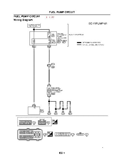
                      FUEL PUMP CIRCUIT
FUEL PUMP CIRCUIT   To ESM
Wiring Diagram


                                          MBWA1102E


                             EC-1
                                          FUEL PUMP CIRCUIT

Specification data are reference values and are measured between each terminal and ground.
CAUTION:
Do not use ECM ground terminals when measuring input/output voltage. Doing so may result in dam-
age to the ECM's transistor. Use a ground other than ECM terminals, such as the ground.
 TER-
                 WIRE
 MINAL                         ITEM                            CONDITION                               DATA (DC Voltage)
                COLOR
  NO.
                                          [Ignition switch ON]
                                          q   For 1 second after turning ignition switch ON      0 - 1.0V
                                          [Engine is running]
     113    R           Fuel pump relay
                                          [Ignition switch ON]
                                                                                                 BATTERY VOLTAGE
                                          q   More than 1 second after turning ignition switch   (11 - 14V)
                                              ON

Diagnostic Procedure                             To ESM
1. CHECK OVERALL FUNCTION
1.    Turn ignition switch ON.
2. Pinch fuel feed hose with two fingers.
   Fuel pressure pulsation should be felt on the fuel hose for 1
   second after ignition switch is turned ON.
OK or NG
 OK    >> INSPECTION END
 NG    >> GO TO 2.


                                                                                                                     MBIB0310E


2. CHECK FUEL PUMP RELAY POWER SUPPLY CIRCUIT
1.    Turn ignition switch OFF.
2.    Disconnect ECM harness connector.
3.    Turn ignition switch ON.
4.    Check voltage between ECM terminals 113 and ground with
      CONSULT-II or tester.
           Voltage: Battery voltage
OK or NG
 OK    >> GO TO 5.
 NG    >> GO TO 3.


                                                                                                                     PBIB1187E


                                                          EC-2
                                        FUEL PUMP CIRCUIT

3. CHECK FUEL PUMP POWER SUPPLY CIRCUIT-I
1.   Turn ignition switch OFF.
2.   Disconnect IPDM E/R harness connector E17.
3.   Turn ignition switch ON.
4.   Check voltage between IPDM E/R terminal 69 and ground with
     CONSULT-II or tester.
        Voltage: Battery voltage
OK or NG
 OK    >> GO TO 4.
 NG    >> GO TO 8.


                                                                                                 MBIB0312E


4. DETECT MALFUNCTIONING PART
Check the following.
q  IPDM E/R connector E17
q  Harness for open or short between IPDM E/R and ECM

         >> Repair harness or connectors.

5. CHECK FUEL PUMP POWER SUPPLY AND GROUND CIRCUIT FOR OPEN AND SHORT
1.   Turn ignition switch OFF.
2.   Disconnect "fuel level sensor unit and fuel pump" harness con-
     nector.
3.   Disconnect IPDM E/R harness connector E13.
4.   Check harness continuity between IPDM E/R connector E13 ter-
     minal 20 and "fuel level sensor unit and fuel pump" terminal 1,
     "fuel level sensor unit and fuel pump" terminal 3 and body
     ground.
     Refer to Wiring Diagram.
        Continuity should exist.
                                                                                                 MBIB0288E
5. Also check harness for short to ground and short to power.
OK or NG
 OK    >> GO TO 7.
 NG    >> GO TO 6.

6. DETECT MALFUNCTIONING PART
Check the following.
q  Harness connectors B59, E112
q  Harness for open or short between "fuel level sensor unit and fuel pump" and IPDM E/R
q  Harness for open or short between "fuel level sensor unit and fuel pump" and body ground

         >> Repair open circuit or short to ground or short to power in harness or connectors.


                                                   EC-3
                                    FUEL PUMP CIRCUIT

7. CHECK FUEL PUMP
Refer to EC-830 "Component Inspection" on ESM.
OK or NG
 OK      >> GO TO 8.
 NG      >> Replace fuel pump.

8. CHECK INTERMITTENT INCIDENT
Refer to EC-566 "TROUBLE DIAGNOSIS FOR INTERMITTENT INCIDENT" on ESM.
OK or NG
 OK      >> Replace IPDM E/R
 NG      >> Repair or replace harness or connector
         >> INSPECTION END


                                                 EC-4
◦ Jabse Service Manual Search 2024 ◦ Jabse Pravopis ◦ onTap.bg ◦ Other service manual resources online : Fixya ◦ eServiceinfo