Service Manuals, User Guides, Schematic Diagrams or docs for : . Car Manuals Nissan Micra 2003-2006 Approved sma LT-002
<< Back | HomeMost service manuals and schematics are PDF files, so You will need Adobre Acrobat Reader to view : Acrobat Download Some of the files are DjVu format. Readers and resources available here : DjVu Resources
For the compressed files, most common are zip and rar. Please, extract files with Your favorite compression software ( WinZip, WinRAR ... ) before viewing. If a document has multiple parts, You should download all, before extracting.
Good luck. Repair on Your own risk. Make sure You know what You are doing.
Image preview - the first page of the document
>> Download LT-002 documenatation <<
Text preview - extract from the document
                             REAR FOG LAMP
REAR FOG LAMP
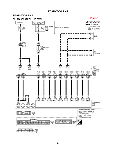
Wiring Diagram -- R/FOG --                   To ESM


                                                 MKWA1529E


                                 LT-1
REAR FOG LAMP


                MKWA3080E


    LT-2
           TURN SIGNAL AND HAZARD WARNING LAMPS
TURN SIGNAL AND HAZARD WARNING LAMPS
Wiring Diagram -- TURN --                         To ESM


                                                     MKWA1444E


                            LT-3
TURN SIGNAL AND HAZARD WARNING LAMPS


                                       MKWA3081E


                LT-4
             PARKING, LICENSE PLATE AND TAIL LAMPS
PARKING, LICENSE PLATE AND TAIL LAMPS
Wiring Diagram -- TAIL/L --                          To ESM


                                                        MKWA1525E


                              LT-5
PARKING, LICENSE PLATE AND TAIL LAMPS


                                        MKWA1441E


                LT-6
PARKING, LICENSE PLATE AND TAIL LAMPS


                                        MKWA3082E


                LT-7
                             STOP LAMP
STOP LAMP
Wiring Diagram-- STOP/L --               To ESM


                                              MKWA3083E


                               LT-8
                              BACK-UP LAMP
BACK-UP LAMP
Wiring Diagram -- BACK/L --                  To ESM


                                                  MKWA1443E


                                  LT-9
BACK-UP LAMP


               MKWA3084E


   LT-10
                                            ILLUMINATION
ILLUMINATION
System Description                                                                               To ESM
The illumination lamps operation is controlled by the lighting switch which built into the combination switch,
BCM and IPDM E/R.Tail lamp relay is built into IPDM E/R.BCM read combination switch condition. Refer to LT-
189, "System Description" on ESM.
Power is supplied at all times
q   to tail lamp relay (located in the IPDM E/R).
Power is also supplied at all times
q   to BCM terminals 74 and 79
q   through 40A fusible link (letter J, located in the fuse and fusible link box).
With the ignition switch in the ON or START position, power is supplied
q   to BCM terminal 24
q   through 10A fuse [No. 4, located in the fuse block (J/B)].
q   to power window main switch terminal 5
q   to front power window switch (passenger side) terminal 1
q   through BCM terminal 78
Ground is supplied
q   to BCM terminals 2 and 70
q   through grounds M19, and M20.
ILLUMINATION OPERATION BY LIGHTING SWITCH
When the lighting switch is turned to 1ST position, BCM read combination switch condition. Refer to LT-189,
"System Description" on ESM. And BCM send illumination lamp request signal to IPDM E/R via CAN commu-
nication line. Then IPDM E/R is turned on tail lamp relay. Tail lamp relay is energized and then power is sup-
plied:
q    through terminal 15 of the IPDM E/R
q    to heated seat switch driver side (illumination) terminal 5
q    to heated seat switch passenger side (illumination) terminal 5
q    through terminal 16 of the IPDM E/R
q    to audio unit terminal 36
q    to audio and navi control unit terminal 36
q    to heater control panel terminal 15
q    to A/C auto amplifier terminal 11
q    to headlamp aiming switch terminal 3
q    to headlamp washer switch terminal 3
q    to hazard switch terminal 3
q    to ashtray illumination terminal 1 and
q    to A/T device terminal 5
q    to ESP OFF switch terminal 3
Ground is supplied at all times
q    to heated seat switch driver side terminal 6
q    to heated seat switch passenger side terminal 6
q    through body grounds B17, B23, B44 and B51
q    to heater control panel terminal 7
q    to A/C auto amplifier terminal 12
q    to headlamp aiming switch terminal 4
q    to headlamp washer switch terminal 4
q    to hazard switch terminal 4
q    to ashtray illumination terminal 2
q    to A/T device terminal 4

                                                  LT-11
                                            ILLUMINATION
q   to power window main switch terminal 7
q   to front power window switch (passenger side) terminal 7
q   to ESP OFF switch terminal 4
q   through body grounds M19 and M20
q   to audio unit terminal 36
q   to audio and navi control unit terminal 36
q   through body ground M60
With power and ground supplied, illumination lamps illuminate.
COMBINATION SWITCH READING FUNCTION
Refer to LT-189, "System Description" on ESM.


                                                  LT-12
            ILLUMINATION
Schematic                  To ESM


                              MKWA3086E


               LT-13
                           ILLUMINATION
Wiring Diagram -- ILL --                  To ESM


                                              MKWA1530E


                              LT-14
ILLUMINATION


               MKWA3088E


   LT-15
ILLUMINATION


               MKWA1748E


   LT-16
ILLUMINATION


               MKWA3089E


   LT-17
ILLUMINATION


               MKWA1531E


   LT-18
ILLUMINATION


               MKWA1759E


   LT-19
ILLUMINATION


               MKWA3296E


   LT-20
◦ Jabse Service Manual Search 2026 ◦ Jabse Pravopis ◦ onTap.bg ◦ Other service manual resources online : Fixya ◦ eServiceinfo