Service Manuals, User Guides, Schematic Diagrams or docs for : . Car Manuals Nissan Almera 2000-2003.2006 Approved Nissan Almera 2000 N16 cl
<< Back | HomeMost service manuals and schematics are PDF files, so You will need Adobre Acrobat Reader to view : Acrobat Download Some of the files are DjVu format. Readers and resources available here : DjVu Resources
For the compressed files, most common are zip and rar. Please, extract files with Your favorite compression software ( WinZip, WinRAR ... ) before viewing. If a document has multiple parts, You should download all, before extracting.
Good luck. Repair on Your own risk. Make sure You know what You are doing.
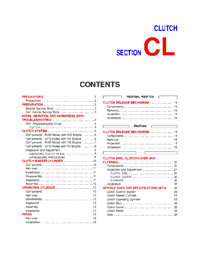
Image preview - the first page of the document
>> Download cl documenatation <<
Text preview - extract from the document
CLUTCH
SECTION CL
CONTENTS
PRECAUTIONS ...............................................................2 RS5F30A, RS5F70A
Precautions ..................................................................2
CLUTCH RELEASE MECHANISM ...............................16
PREPARATION ...............................................................3
Components...............................................................16
Special Service Tools ..................................................3
Removal.....................................................................16
Commercial Service Tools ...........................................3
Inspection...................................................................16
NOISE, VIBRATION AND HARSHNESS (NVH)
Installation..................................................................16
TROUBLESHOOTING .....................................................4
NVH Troubleshooting Chart.........................................4
CLUTCH ...................................................................4 RS5F50A
CLUTCH SYSTEM...........................................................5 CLUTCH RELEASE MECHANISM ...............................19
Components - RHD Model with QG Engine - .............5 Components...............................................................19
Components - LHD Model with QG Engine -..............6 Removal.....................................................................19
Components - RHD Model with YD Engine -..............7 Inspection...................................................................19
Components - LHD Model with YD Engine - ..............8 Installation..................................................................19
Inspection and Adjustment ..........................................9
ADJUSTING CLUTCH PEDAL ....................................9
AIR BLEEDING PROCEDURE ....................................9 CLUTCH DISC, CLUTCH COVER AND
CLUTCH MASTER CYLINDER.....................................10 FLYWHEEL....................................................................21
Components...............................................................10 Components...............................................................21
Removal.....................................................................11 Inspection and Adjustment ........................................21
Installation..................................................................11 CLUTCH DISC.........................................................21
Disassembly...............................................................11 CLUTCH COVER .....................................................22
Inspection...................................................................11 FLYWHEEL .............................................................22
Assembly ...................................................................12 Installation..................................................................22
OPERATING CYLINDER...............................................13 SERVICE DATA AND SPECIFICATIONS (SDS) .........23
Components...............................................................13 Clutch Control System...............................................23
Removal.....................................................................13 Clutch Master Cylinder ..............................................23
Disassembly...............................................................13 Clutch Operating Cylinder .........................................23
Inspection...................................................................13 Clutch Disc.................................................................23
Assembly ...................................................................14 Clutch Cover ..............................................................23
Installation..................................................................14 Clutch Pedal ..............................................................23
PIPING ...........................................................................15 Note ...........................................................................24
Removal.....................................................................15
Installation..................................................................15
PRECAUTIONS
Precautions
Precautions NJCL0001
+ Recommended fluid is brake fluid "DOT 3" or "DOT 4"
(Europe). Refer to MA-16, "Fluid and Lubricants".
+ Never reuse drained brake fluid.
+ Be careful not to splash brake fluid on painted areas.
+ When removing and installing clutch piping, use Tool.
+ Use new brake fluid to clean or wash all parts of master
cylinder and operating cylinder.
+ Never use mineral oils such as gasoline or kerosene. It will
ruin the rubber parts of the hydraulic system.
SBR820BA
WARNING:
After cleaning clutch disc, wipe it with a dust collector. Do not
use compressed air.
CL-2
PREPARATION
Special Service Tools
Special Service Tools NJCL0002
Tool number
Description
Tool name
GG94310000 Removing and installing clutch piping
Flare nut torque wrench a: 10 mm (0.39 in)
NT406
KV30101600 (New) Installing clutch cover and clutch disc
KV30101000 (Former) (F30A and F70A)
Clutch aligning bar a: 15.9 mm (0.626 in) dia.
b: 17.9 mm (0.705 in) dia.
c: 40 mm (1.57 in)
NT645
ST20630000 Installing clutch cover and clutch disc
Clutch aligning bar (F50A)
a: 15.8 mm (0.622 in) dia.
b: 22.9 mm (0.902 in) dia.
c: 45.0 mm (1.772 in)
NT405
ST20050240 Adjusting unevenness of diaphragm spring of
Diaphragm spring adjust- clutch cover
ing wrench a: 150 mm (5.91 in)
b: 25 mm (0.98 in)
NT404
KV32101000 Removing and installing spring pin
Pin punch a: 4 mm (0.16 in) dia.
NT410
Commercial Service Tools NJCL0003
Tool name Description
1 Flare nut crowfoot Removing and installing clutch piping
2 Torque wrench a: 10 mm (0.39 in)
NT360
CL-3
NVH
Symptom
CLUTCH
Reference page
(Possible cause)
gage
SUSPECTED PARTS
Clutch slips
Clutch noisy
Clutch pedal spongy
Clutch grabs/chatters
Clutch does not disen-
1
1
CLUTCH PEDAL (Free play out of adjustment) CL-9
2
1
CLUTCH LINE (Air in line) CL-9
3
2
MASTER CYLINDER PISTON CUP (Damaged) CL-10
4
2
OPERATING CYLINDER PISTON CUP (Damaged) CL-13
tion. If necessary, repair or replace these parts.
Refer to EM-136, "Removal and Installation" (QG engine model) and
1
ENGINE MOUNTING (Loose)
EM-50, "Removal and Installation" (YD engine model).
1
RELEASE BEARING (Worn, dirty or damaged) CL-16 (RS5F30A, RS5F70A), CL-19 (RS5F50A)
CL-4
5
CLUTCH DISC (Out of true) CL-21
5
2
CLUTCH DISC (Runout is excessive) CL-21
5
CLUTCH DISC (Lining broken) CL-21
5
CLUTCH DISC (Dirty or burned) CL-21
5
2
2
CLUTCH DISC (Oily) CL-21
NVH Troubleshooting Chart
2
2
CLUTCH DISC (Worn out) CL-21
2
CLUTCH DISC (Hardened) CL-21
5
CLUTCH DISC (Lack of spline grease) CL-21
6
3
DIAPHRAGM SPRING (Damaged) CL-22
6
2
DIAPHRAGM SPRING (Out of tip alignment) CL-22
NOISE, VIBRATION AND HARSHNESS (NVH) TROUBLESHOOTING
7
4
PRESSURE PLATE (Distortion) CL-22
5
FLYWHEEL (Distortion) CL-22
NJCL0004S0101
NJCL0004S01
NJCL0004
Use the chart below to help you find the cause of the symptom. The numbers indicate the order of the inspec-
CLUTCH SYSTEM
Components -- RHD Model with QG Engine --
Components -- RHD Model with QG Engine -- NJCL0041
SCL843
1. Clutch pedal bracket 11. Bush 21. Clutch disc
2. Pedal stopper bolt 12. Snap pin 22. Clutch cover
3. Bush 13. Fulcrum pin 23. Withdrawal lever
4. Clutch pedal 14. Clutch master cylinder 24. Spacer
5. Bush 15. Nipple 25. Operating cylinder
6. Clevis pin 16. Reservoir cap 26. Clutch hose
7. Assist spring 17. Reservoir tank 27. Clutch lever
8. Return spring 18. Hose clamp 28. Spring pin
9. Bush 19. Hose 29. Release bearing
10. Stopper rubber 20. Washer 30. Release bearing spring
CL-5
CLUTCH SYSTEM
Components -- LHD Model with QG Engine --
Components -- LHD Model with QG Engine -- NJCL0048
SCL844
1. Clutch pedal bracket 9. Reservoir cap 17. Spacer
2. Clevis pin 10. Reservoir tank 18. Operating cylinder
3. Bush 11. Hose clamp 19. Clutch hose
4. Snap pin 12. Hose 20. Clutch lever
5. Pedal stopper bolt 13. Washer 21. Spring pin
6. Clutch pedal 14. Clutch disc 22. Release bearing
7. Clutch master cylinder 15. Clutch cover 23. Release bearing spring
8. Nipple 16. Withdrawal lever
CL-6
CLUTCH SYSTEM
Components -- RHD Model with YD Engine --
Components -- RHD Model with YD Engine -- NJCL0005
SCL845
1. Clutch pedal bracket 11. Snap pin 20. Air bleeder screw
2. Pedal stopper bolt 12. Fulcrum pin 21. Withdrawal lever
3. Bush 13. Clutch master cylinder 22. Operating cylinder
4. Clutch pedal 14. Nipple 23. Clutch hose
5. Bush 15. Reservoir cap 24. Clutch disc
6. Clevis pin 16. Reservoir tank 25. Clutch cover
7. Assist spring 17. Hose clamp 26. Clutch hose connector
8. Bush 18. Hose 27. Release bearing
9. Stopper rubber 19. Washer 28. Washer
10. Bush
CL-7
CLUTCH SYSTEM
Components -- LHD Model with YD Engine --
Components -- LHD Model with YD Engine -- NJCL0049
SCL846
1. Clutch pedal bracket 9. Reservoir cap 16. Operating cylinder
2. Clevis pin 10. Reservoir tank 17. Clutch hose
3. Bush 11. Hose clamp 18. Clutch disc
4. Snap pin 12. Hose 19. Clutch cover
5. Pedal stopper bolt 13. Washer 20. Clutch hose connector
6. Clutch pedal 14. Air bleeder screw 21. Release bearing
7. Clutch master cylinder 15. Withdrawal lever 22. Washer
8. Nipple
CL-8
CLUTCH SYSTEM
Inspection and Adjustment
Inspection and Adjustment NJCL0006
ADJUSTING CLUTCH PEDAL NJCL0006S01
Pedal Height NJCL0006S0101
1. Adjust pedal height with pedal stopper bolt.
Pedal height "H" (RHD model):
169.5 - 179.5 mm (6.67 - 7.07 in)
Pedal height "H" (LHD model):
163.5 - 173.5 mm (6.44 - 6.83 in)
SCL837
2. Adjust pedal free play with master cylinder push rod. Then
tighten lock nut.
Pedal free play "A":
9 - 16 mm (0.35 - 0.63 in)
+ Push or step on clutch pedal until resistance is felt, and check
the distance the pedal moves.
SCL702
AIR BLEEDING PROCEDURE NJCL0006S02
1. Bleed air from clutch operating cylinder according to the fol-
lowing procedure.
+ Carefully monitor fluid level at master cylinder during
bleeding operation.
a. Top up reservoir with recommended brake fluid.
b. Connect a transparent vinyl tube to air bleeder valve.
c. Slowly depress the clutch pedal to its full stroke and release it
completely. Repeat this operation several times at 2 to 3 sec-
onds intervals.
SCL838 d. Open the air bleeder with the clutch pedal fully depressed.
e. Close the air bleeder.
f. Release the clutch pedal and wait at least 5 seconds.
g. Repeat steps c through f mentioned above, then air bubbles
will no longer appear at the damper in the brake fluid.
Air bleeder valve tightening torque:
: 5.9 - 9.8 N◦ Jabse Service Manual Search 2026 ◦ Jabse Pravopis ◦ onTap.bg ◦ Other service manual resources online : Fixya ◦ eServiceinfo