Service Manuals, User Guides, Schematic Diagrams or docs for : . Car Manuals Nissan Almera 2000-2003.2006 Approved Nissan Almera 2001 N16 2001 Nissan Almera at
<< Back | HomeMost service manuals and schematics are PDF files, so You will need Adobre Acrobat Reader to view : Acrobat Download Some of the files are DjVu format. Readers and resources available here : DjVu Resources
For the compressed files, most common are zip and rar. Please, extract files with Your favorite compression software ( WinZip, WinRAR ... ) before viewing. If a document has multiple parts, You should download all, before extracting.
Good luck. Repair on Your own risk. Make sure You know what You are doing.
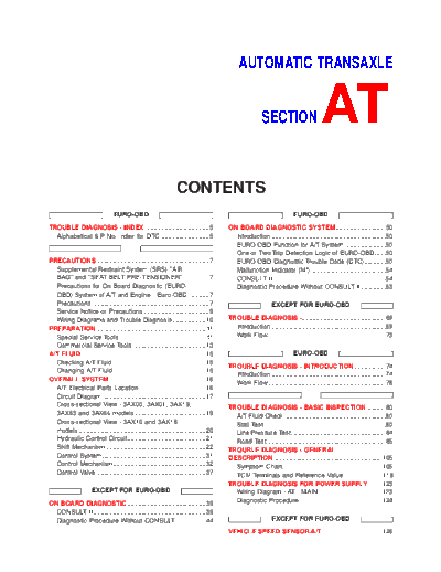
Image preview - the first page of the document
>> Download at documenatation <<
Text preview - extract from the document
AUTOMATIC TRANSAXLE
SECTION AT
CONTENTS
EURO-OBD EURO-OBD
TROUBLE DIAGNOSIS - INDEX ....................................5 ON BOARD DIAGNOSTIC SYSTEM ............................50
Alphabetical & P No. Index for DTC ...........................5 Introduction ................................................................50
EURO-OBD Function for A/T System .......................50
One or Two Trip Detection Logic of EURO-OBD......50
PRECAUTIONS ...............................................................7 EURO-OBD Diagnostic Trouble Code (DTC)............50
Supplemental Restraint System (SRS) AIR Malfunction Indicator (MI) ..........................................54
BAG and SEAT BELT PRE-TENSIONER...............7 CONSULT-II ...............................................................54
Precautions for On Board Diagnostic (EURO- Diagnostic Procedure Without CONSULT-II..............63
OBD) System of A/T and Engine - Euro-OBD -..........7
Precautions ..................................................................7 EXCEPT FOR EURO-OBD
Service Notice or Precautions .....................................9
Wiring Diagrams and Trouble Diagnosis...................10 TROUBLE DIAGNOSIS -...............................................69
PREPARATION .............................................................11 Introduction ................................................................69
Special Service Tools ................................................11 Work Flow..................................................................73
Commercial Service Tools .........................................13
A/T FLUID ......................................................................15 EURO-OBD
Checking A/T Fluid ....................................................15
TROUBLE DIAGNOSIS - INTRODUCTION..................74
Changing A/T Fluid ....................................................15
Introduction ................................................................74
OVERALL SYSTEM ......................................................16
Work Flow..................................................................78
A/T Electrical Parts Location .....................................16
Circuit Diagram ..........................................................17
Cross-sectional View - 3AX00, 3AX01, 3AX19, TROUBLE DIAGNOSIS - BASIC INSPECTION ...........80
3AX63 and 3AX64 models ........................................19 A/T Fluid Check .........................................................80
Cross-sectional View - 3AX10 and 3AX18 Stall Test ....................................................................80
models .......................................................................20 Line Pressure Test.....................................................84
Hydraulic Control Circuit............................................21 Road Test...................................................................85
Shift Mechanism ........................................................22 TROUBLE DIAGNOSIS - GENERAL
Control System ..........................................................31 DESCRIPTION .............................................................105
Control Mechanism....................................................32 Symptom Chart........................................................105
Control Valve .............................................................37 TCM Terminals and Reference Value......................118
TROUBLE DIAGNOSIS FOR POWER SUPPLY........123
EXCEPT FOR EURO-OBD Wiring Diagram - AT - MAIN....................................123
ON BOARD DIAGNOSTIC ............................................39 Diagnostic Procedure ..............................................124
CONSULT-II ...............................................................39
Diagnostic Procedure Without CONSULT-II..............44 EXCEPT FOR EURO-OBD
VEHICLE SPEED SENSOR.A/T..................................126
CONTENTS (Cont'd)
Description ...............................................................126 Wiring Diagram - AT - PNP/SW...............................185
Wiring Diagram - AT - VSSA/T ................................128 Diagnostic Procedure ..............................................186
Diagnostic Procedure ..............................................129 Component Inspection.............................................188
VHCL SPEED SEN.MTR VEHICLE ............................131 DTC P0710 A/T FLUID TEMPERATURE SENSOR
Description ...............................................................131 CIRCUIT .......................................................................189
Wiring Diagram - AT - VSSMTR..............................132 Description ...............................................................189
Diagnostic Procedure ..............................................133 Wiring Diagram - AT - FTS ......................................191
THROTTLE POSITION ................................................134 Diagnostic Procedure ..............................................192
Description ...............................................................134 Component Inspection.............................................194
Wiring Diagram - AT - TPS......................................136 DTC P0720 VEHICLE SPEED SENSOR.A/T..............195
Diagnostic Procedure ..............................................137 Description ...............................................................195
Component Inspection.............................................141 Wiring Diagram - AT - VSSA/T ................................197
SHIFT SOLENOID VALVE A ......................................142 Diagnostic Procedure ..............................................198
Description ...............................................................142 DTC P0725 ENGINE SPEED SIGNAL .......................200
Wiring Diagram - AT - SSV/A ..................................144 Description ...............................................................200
Diagnostic Procedure ..............................................145 Wiring Diagram - AT - ENGSS ................................201
Component Inspection.............................................147 Diagnostic Procedure ..............................................202
SHIFT SOLENOID VALVE B ......................................148 DTC P0731 A/T 1ST GEAR FUNCTION ....................204
Description ...............................................................148 Description ...............................................................204
Wiring Diagram - AT - SSV/B ..................................150 Wiring Diagram - AT - 1ST ......................................207
Diagnostic Procedure ..............................................151 Diagnostic Procedure ..............................................208
Component Inspection.............................................153 Component Inspection.............................................209
OVERRUN CLUTCH SOLENOID................................154 DTC P0732 A/T 2ND GEAR FUNCTION....................211
Description ...............................................................154 Description ...............................................................211
Wiring Diagram - AT - OVRCSV..............................155 Wiring Diagram - AT - 2ND......................................214
Diagnostic Procedure ..............................................156 Diagnostic Procedure ..............................................215
Component Inspection.............................................158 Component Inspection.............................................216
TORQUE CONVERTER CLUTCH...............................159 DTC P0733 A/T 3RD GEAR FUNCTION....................217
Description ...............................................................159 Description ...............................................................217
Wiring Diagram - AT - TCV......................................161 Wiring Diagram - AT - 3RD......................................220
Diagnostic Procedure ..............................................162 Diagnostic Procedure ..............................................221
Component Inspection.............................................164 Component Inspection.............................................222
BATT/FLUID TEMP SEN (A/T FLUID TEMP DTC P0734 A/T 4TH GEAR FUNCTION ....................223
SENSOR CIRCUIT AND TCM POWER SOURCE) ....165 Description ...............................................................223
Description ...............................................................165 Wiring Diagram - AT - 4TH ......................................227
Wiring Diagram - AT - BA/FTS ................................167 Diagnostic Procedure ..............................................228
Diagnostic Procedure ..............................................168 Component Inspection.............................................232
Component Inspection.............................................171 DTC P0740 TORQUE CONVERTER CLUTCH
ENGINE SPEED SIGNAL............................................172 SOLENOID VALVE......................................................233
Description ...............................................................172 Description ...............................................................233
Wiring Diagram - AT - ENGSS ................................173 Wiring Diagram - AT - TCV......................................235
Diagnostic Procedure ..............................................174 Diagnostic Procedure ..............................................236
LINE PRESSURE SOLENOID ....................................176 Component Inspection.............................................238
Description ...............................................................176 DTC P0745 LINE PRESSURE SOLENOID VALVE ...239
Wiring Diagram - AT - LPSV....................................178 Description ...............................................................239
Diagnostic Procedure ..............................................179 Wiring Diagram - AT - LPSV....................................241
Component Inspection.............................................182 Diagnostic Procedure ..............................................242
Component Inspection.............................................245
EURO-OBD DTC P0750 SHIFT SOLENOID VALVE A ..................246
Description ...............................................................246
DTC P0705 PARK/NEUTRAL POSITION (PNP) Wiring Diagram - AT - SSV/A ..................................248
SWITCH .......................................................................183 Diagnostic Procedure ..............................................249
Description ...............................................................183
AT-2
CONTENTS (Cont'd)
Component Inspection.............................................251 8. Vehicle Cannot Be Started From D1 ...................311
DTC P0755 SHIFT SOLENOID VALVE B ..................252 9. A/T Does Not Shift: D1 -> D2 Or Does Not
Description ...............................................................252 Kickdown: D4 -> D2..................................................314
Wiring Diagram - AT - SSV/B ..................................254 10. A/T Does Not Shift: D2 -> D3.............................317
Diagnostic Procedure ..............................................255 11. A/T Does Not Shift: D3 -> D4 .............................320
Component Inspection.............................................257 12. A/T Does Not Perform Lock-up .........................323
DTC P1705 THROTTLE POSITION SENSOR ...........258 13. A/T Does Not Hold Lock-up Condition ..............325
Description ...............................................................258 14. Lock-up Is Not Released...................................327
Wiring Diagram - AT - TPS......................................261 15. Engine Speed Does Not Return To Idle (Light
Diagnostic Procedure ..............................................263 Braking D4 -> D3).....................................................328
Component Inspection.............................................267 16. Vehicle Does Not Start From D1 .......................330
DTC P1760 OVERRUN CLUTCH SOLENOID 17. A/T Does Not Shift: D4 -> D3, When
VALVE..........................................................................268 Overdrive Control Switch ON -> OFF ...............331
Description ...............................................................268 18. A/T Does Not Shift: D3 -> 22, When Selector
Wiring Diagram - AT - OVRCSV..............................270 Lever D -> 2 Position.........................................332
Diagnostic Procedure ..............................................271 19. A/T Does Not Shift: 22 -> 11, When Selector
Component Inspection.............................................273 Lever 2 -> 1 Position .........................................333
DTC BATT/FLUID TEMP SEN (A/T FLUID TEMP 20. Vehicle Does Not Decelerate By Engine
SENSOR CIRCUIT AND TCM POWER SOURCE) ....274 Brake........................................................................334
Description ...............................................................274 21. TCM Self-diagnosis Does Not Activate (PNP,
Wiring Diagram - AT - BA/FTS ................................276 Overdrive Control and Throttle Position Switches
Diagnostic Procedure ..............................................277 Circuit Checks) ........................................................334
Component Inspection.............................................280 A/T SHIFT LOCK SYSTEM.........................................343
DTC VHCL SPEED SEN.MTR VEHICLE SPEED Description ...............................................................343
SENSOR.MTR..............................................................281 Shift Lock System Electrical Parts Location............343
Description ...............................................................281 Wiring Diagram - SHIFT -........................................344
Wiring Diagram - AT - VSSMTR..............................283 Diagnostic Procedure ..............................................345
Diagnostic Procedure ..............................................285 KEY INTERLOCK CABLE ..........................................349
Components.............................................................349
Removal...................................................................349
DTC CONTROL UNIT (RAM), CONTROL UNIT Installation................................................................350
(ROM)...........................................................................286 ON-VEHICLE SERVICE ..............................................351
Description ...............................................................286 Control Valve Assembly and Accumulators.............351
Diagnostic Procedure ..............................................286 Control Cable Adjustment........................................352
DTC CONTROL UNIT (EEP ROM) .............................288 Park/Neutral Position (PNP) Switch Adjustment .....352
Description ...............................................................288 Differential Side Oil Seal Replacement ...................353
Diagnostic Procedure ..............................................289 Revolution Sensor Replacement .............................353
TROUBLE DIAGNOSES FOR SYMPTOMS ...............290 REMOVAL AND INSTALLATION ...............................354
Wiring Diagram - AT - NONDTC/General and Removal...................................................................354
Except for Euro-OBD...............................................290 Installation................................................................355
Wiring Diagram - AT - NONDTC/EURO-OBD .........292 OVERHAUL .................................................................357
1. O/D OFF Indicator Lamp Does Not Come On....296 Components-1 3AX00, 3AX01, 3AX19, 3AX63
2. Engine Cannot Be Started In P and N and 3AX64 models ..................................................357
Position ....................................................................299 Components-1 3AX10 and 3AX18 models .............358
3. In P Position, Vehicle Moves Forward Or Components-2 3AX00, 3AX01, 3AX19, 3AX63
Backward When Pushed .........................................300 and 3AX64 models ..................................................359
4. In N Position, Vehicle Moves ...........................301 Components-2 3AX10 and 3AX18 models .............360
5. Large Shock. N -> R Position .......................303 Components-3 3AX00, 3AX01, 3AX19, 3AX63
6. Vehicle Does Not Creep Backward In R and 3AX64 models ..................................................361
Position ....................................................................305 Components-3 3AX10 and 3AX18 models .............362
7. Vehicle Does Not Creep Forward In D, 2 Oil Channel ..............................................................363
Or 1 Position.........................................................308
AT-3
CONTENTS (Cont'd)
Locations of Adjusting Shims, Needle Bearings, Adjustment (2) .........................................................459
Thrust Washers and Snap Rings - 3AX00, 01, Assembly (3)............................................................462
19, 63 and 64 models..............................................364 Assembly (4)............................................................465
Locations of Adjusting Shims, Needle Bearings, SERVICE DATA AND SPECIFICATIONS (SDS) .......470
Thrust Washers and Snap Rings - 3AX10 and General Specifications.............................................470
3AX18 models .........................................................365 Shift Schedule..........................................................470
DISASSEMBLY............................................................366 Stall Revolution........................................................473
REPAIR FOR COMPONENT PARTS .........................381 Line Pressure...........................................................473
Manual Shaft............................................................381 Control Valves..........................................................474
Oil Pump ..................................................................384 Clutch and Brakes ...................................................474
Control Valve Assembly...........................................388 Clutch and Brake Return Springs............................477
Control Valve Upper Body .......................................397 Oil Pump ..................................................................477
Control Valve Lower Body .......................................401 Input Shaft ...............................................................478
Reverse Clutch ........................................................403 Planetary Carrier......................................................478
High Clutch ..............................................................407 Final Drive................................................................478
Forward Clutch and Overrun Clutch........................412 Reduction Pinion Gear ............................................480
Low & Reverse Brake..............................................419 Output Shaft - 3AX00, 3AX01, 3AX19, 3AX63
Rear Internal Gear, Forward Clutch Hub and and 3AX64 models ..................................................481
Overrun Clutch Hub.................................................423 Output Shaft - 3AX10 and 3AX18 models ..............483
O/Shaft, O/Gear, I/Gear, R/Pinion Gear and B/ Bearing Retainer......................................................484
Retainer - 3AX00, 01, 19, 63 and 64 models .........427 Total End Play..........................................................484
Output Shaft, Idler Gear, Reduction Pinion Gear Reverse Clutch End Play ........................................484
and Bearing Retainer - 3AX10 and 3AX18 Accumulator .............................................................484
models .....................................................................432 Band Servo ..............................................................485
Band Servo Piston Assembly ..................................437 Removal and Installation .........................................485
Final Drive................................................................442 Shift Solenoid Valves...............................................485
ASSEMBLY..................................................................446 Resistance ...............................................................485
Assembly (1)............................................................446 ATF Temp. Sensor ...................................................485
Adjustment (1) .........................................................447 Revolution Sensor ...................................................485
Assembly (2)............................................................455 Dropping Resistor ....................................................485
AT-4
TROUBLE DIAGNOSIS -- INDEX EURO-OBD
Alphabetical & P No. Index for DTC
Alphabetical & P No. Index for DTC NJAT0243
ALPHABETICAL INDEX FOR DTC NJAT0243S01
Check if the vehicle is a model with Euro-OBD system or not by the
"Type approval number" on the identification plate. Refer to GI-40,
"IDENTIFICATION PLATE".
Type approval number Model
Available With Euro-OBD system
Not available (blank) Without Euro-OBD system
DTC
Items
CONSULT-II Reference page
(CONSULT-II screen terms)
GST*1
A/T 1ST GR FNCTN P0731 AT-204
A/T 2ND GR FNCTN P0732 AT-211
A/T 3RD GR FNCTN P0733 AT-217
A/T 4TH GR FNCTN P0734 AT-223
ATF TEMP SEN/CIRC P0710 AT-189
ENGINE SPEED SIG P0725 AT-200
L/PRESS SOL/CIRC P0745 AT-239
O/R CLTCH SOL/CIRC P1760 AT-268
PNP SW/CIRC P0705 AT-183
SFT SOL A/CIRC*2 P0750 AT-246
SFT SOL B/CIRC*2 P0755 AT-252
TCC SOLENOID/CIRC P0740 AT-233
TP SEN/CIRC A/T*2 P1705 AT-258
VEH SPD SEN/CIR AT*3 P0720 AT-195
*1: These numbers are prescribed by SAE J2012.
*2: When the fail-safe operation occurs, the MIL illuminates.
*3: The MIL illuminates when both the "Revolution sensor signal" and the "Vehicle speed sensor signal" meet the fail-safe condition at
the same time.
AT-5
TROUBLE DIAGNOSIS -- INDEX EURO-OBD
Alphabetical & P No. Index for DTC (Cont'd)
P NO. INDEX FOR DTC =NJAT0243S02
Check if the vehicle is a model with Euro-OBD system or not by the
"Type approval number" on the identification plate. Refer to GI-40,
"IDENTIFICATION PLATE".
Type approval number Model
Available With Euro-OBD system
Not available (blank) Without Euro-OBD system
DTC
Items
CONSULT-II Reference page
(CONSULT-II screen terms)
GST*1
P0705 PNP SW/CIRC AT-183
P0710 ATF TEMP SEN/CIRC AT-189
P0720 VEH SPD SEN/CIR AT*3 AT-195
P0725 ENGINE SPEED SIG AT-200
P0731 A/T 1ST GR FNCTN AT-204
P0732 A/T 2ND GR FNCTN AT-211
P0733 A/T 3RD GR FNCTN AT-217
P0734 A/T 4TH GR FNCTN AT-223
P0740 TCC SOLENOID/CIRC AT-233
P0745 L/PRESS SOL/CIRC AT-239
P0750 SFT SOL A/CIRC*2 AT-246
P0755 SFT SOL B/CIRC*2 AT-252
P1705 TP SEN/CIRC A/T*2 AT-258
P1760 O/R CLTCH SOL/CIRC AT-268
*1: These numbers are prescribed by SAE J2012.
*2: When the fail-safe operation occurs, the MIL illuminates.
*3: The MIL illuminates when both the "Revolution sensor signal" and the "Vehicle speed sensor signal" meet the fail-safe condition at
the same time.
AT-6
PRECAUTIONS
Supplemental Restraint System (SRS) "AIR BAG" and "SEAT BELT PRE-TENSIONER"
Supplemental Restraint System (SRS) "AIR
BAG" and "SEAT BELT PRE-TENSIONER" NJAT0249
The Supplemental Restraint System such as "AIR BAG" and "SEAT BELT PRE-TENSIONER" used along with
a seat belt, helps to reduce the risk or severity of injury to the driver and front passenger for certain types of
collision. The SRS system composition which is available to NISSAN MODEL N16 is as follows (The compo-
sition varies according to the destination and optional equipment.):
+ For a frontal collision
The Supplemental Restraint System consists of driver air bag module (located in the center of the steer-
ing wheel), front passenger air bag module (located on the instrument panel on passenger side), front seat
belt pre-tensioners, a diagnosis sensor unit, warning lamp, wiring harness and spiral cable.
+ For a side collision
The Supplemental Restraint System consists of front side air bag module (located in the outer side of front
seat), side air bag (satellite) sensor, diagnosis sensor unit (one of components of air bags for a frontal
collision), wiring harness, warning lamp (one of components of air bags for a frontal collision).
Information necessary to service the system safely is included in the RS section of this Service Manual.
WARNING:
+ To avoid rendering the SRS inoperative, which could increase the risk of personal injury or death
in the event of a collision which would result in air bag inflation, all maintenance should be per-
formed by an authorized NISSAN dealer.
+ Improper maintenance, including incorrect removal and installation of the SRS, can lead to per-
sonal injury caused by unintentional activation of the system. For removal of Spiral Cable and Air
Bag Module, see the RS section.
+ Do not use electrical test equipment on any circuit related to the SRS unless instructed to in this
Service Manual. Spiral cable and wiring harnesses covered with yellow insulation tape either just
before the harness connectors or for the complete harness are related to the SRS.
Precautions for On Board Diagnostic (EURO-
OBD) System of A/T and Engine -- Euro-OBD
-- NJAT0245
The ECM has an on board diagnostic system. It will light up the malfunction indicator lamp (MIL) to warn the
driver of a malfunction causing emission deterioration.
CAUTION:
+ Be sure to turn the ignition switch "OFF" and disconnect the negative battery terminal before any
repair or inspection work. The open/short circuit of related switches, sensors, solenoid valves, etc.
will cause the MIL to light up.
+ Be sure to connect and lock the connectors securely after work. A loose (unlocked) connector will
cause the MIL to light up due to an open circuit. (Be sure the connector is free from water, grease,
dirt, bent terminals, etc.)
+ Be sure to route and secure the harnesses properly after work. Interference of the harness with a
bracket, etc. may cause the MIL to light up due to a short circuit.
+ Be sure to connect rubber tubes properly after work. A misconnected or disconnected rubber tube
may cause the MIL to light up due to a malfunction of the EGR system or fuel injection system,
etc.
+ Be sure to erase the unnecessary malfunction information (repairs completed) from the TCM and
ECM before returning the vehicle to the customer.
Precautions NJAT0246
+ Before connecting or disconnecting the TCM harness
connector, turn ignition switch OFF and disconnect nega-
tive battery terminal. Failure to do so may damage the
TCM. Because battery voltage is applied to TCM even if
ignition switch is turned off.
SEF289H
AT-7
PRECAUTIONS
Precautions (Cont'd)
+ When connecting or disconnecting pin connectors into or
from TCM, take care not to damage pin terminals (bend or
break).
Make sure that there are not any bends or breaks on TCM
pin terminal, when connecting pin connectors.
AAT470A
+ Before replacing TCM, perform TCM input/output signal
inspection and make sure whether TCM functions prop-
erly or not. (See page AT-118.)
MEF040DA
+ After performing each TROUBLE DIAGNOSIS, perform
"DTC (Diagnostic Trouble Code) CONFIRMATION PROCE-
DURE".
The DTC should not be displayed in the "DTC CONFIRMA-
TION PROCEDURE" if the repair is completed.
SAT964I
+ Before proceeding with disassembly, thoroughly clean the out-
side of the transaxle. It is important to prevent the internal parts
from becoming contaminated by dirt or other foreign matter.
+ Disassembly should be done in a clean work area.
+ Use lint-free cloth or towels for wiping parts clean. Common
shop rags can leave fibers that could interfere with the opera-
tion of the transaxle.
+ Place disassembled parts in order for easier and proper
assembly.
+ All parts should be carefully cleaned with a general purpose,
non-flammable solvent before inspection or reassembly.
+ Gaskets, seals and O-rings should be replaced any time the
transaxle is disassembled.
+ It is very important to perform functional tests whenever they
are indicated.
+ The valve body contains precision parts and requires extreme
care when parts are removed and serviced. Place disas-
sembled valve body parts in order for easier and proper
assembly. Care will also prevent springs and small parts from
becoming scattered or lost.
+ Properly installed valves, sleeves, plugs, etc. will slide along
bores in valve body under their own weight.
+ Before assembly, apply a coat of recommended ATF to all
AT-8
PRECAUTIONS
Precautions (Cont'd)
parts. Apply petroleum jelly to protect O-rings and seals, or
hold bearings and washers in place during assembly. Do not
use grease.
+ Extreme care should be taken to avoid damage to O-rings,
seals and gaskets when assembling.
+ After overhaul, refill the transaxle with new ATF.
+ When the A/T drain plug is removed, only some of the fluid is
drained. Old A/T fluid will remain in torque converter and ATF
cooling system.
Always follow the procedures under "Changing A/T Fluid" in the
AT section when changing A/T fluid. Refer to "Changing A/T
Fluid", AT-15.
Service Notice or Precautions NJAT0247
FAIL-SAFE NJAT0247S01
The TCM has an electronic Fail-Safe (limp home mode). This allows the vehicle to be driven even if a major
electrical input/output device circuit is damaged.
Under Fail-Safe, the vehicle always runs in third gear, even with a shift lever position of "1", "2" or "D". The
customer may complain of sluggish or poor acceleration.
When the ignition key is turned "ON" following Fail-Safe operation, O/D OFF indicator lamp blinks for about
8 seconds. (For GENERAL AND EXCEPT FOR EURO-OBD; "SELF-DIAGNOSTIC PROCEDURE (WITHOUT
CONSULT-II)", refer to AT-44 and for EURO-OBD; "TCM SELF-DIAGNOSTIC PROCEDURE (No Tools)", refer
to AT-63.)
Fail-Safe may occur without electrical circuit damage if the vehicle is driven under extreme conditions (such
as excessive wheel spin followed by sudden braking). To recover normal shift pattern, turn the ignition key
"OFF" for 5 seconds, then "ON".
The blinking of the O/D OFF indicator lamp for about 8 seconds will appear only once and be cleared. The
customer may resume normal driving conditions.
Always follow the "WORK FLOW" [Refer to AT-73 (General and except for Euro-OBD), AT-78 (EURO-OBD).]
The SELF-DIAGNOSIS results will be as follows:
The first SELF-DIAGNOSIS will indicate damage to the vehicle speed sensor or the revolution sensor.
During the next SELF-DIAGNOSIS, performed after checking the sensor, no damages will be indicated.
TORQUE CONVERTER SERVICE NJAT0247S02
The torque converter should be replaced under any of the following conditions:
+ External leaks in the hub weld area.
+ Converter hub is scored or damaged.
+ Converter pilot is broken, damaged or fits poorly into crankshaft.
+ Steel particles are found after flushing the cooler and cooler lines.
+ Pump is damaged or steel particles are found in the converter.
+ Vehicle has TCC shudder and/or no TCC apply. Replace only after all hydraulic and electrical diagnoses
have been made. (Converter clutch material may be glazed.)
+ Converter is contaminated with engine coolant containing antifreeze.
+ Internal failure of stator roller clutch.
+ Heavy clutch debris due to overheating (blue converter).
+ Steel particles or clutch lining material found in fluid filter or on magnet when no internal parts in unit are
worn or damaged -- indicates that lining material came from converter.
AT-9
PRECAUTIONS
Service Notice or Precautions (Cont'd)
The torque converter should not be replaced if:
+ The fluid has an odor, is discolored, and there is no evidence of metal or clutch facing particles.
+ The threads in one or more of the converter bolt holes are damaged.
+ Transaxle failure did not display evidence of damaged or worn internal parts, steel particles or clutch plate
lining material in unit and inside the fluid filter.
+ Vehicle has been exposed to high mileage (only). The exception may be where the torque converter clutch
dampener plate lining has seen excess wear by vehicles operated in heavy and/or constant traffic, such
as taxi, delivery or police use.
EURO-OBD SELF-DIAGNOSIS -- EURO-OBD -- NJAT0247S04
+ A/T self-diagnosis is performed by the TCM in combination with the ECM. The results can be read through
the blinking pattern of the O/D OFF indicator or the malfunction indicator (MI). Refer to the table on AT-55
for the indicator used to display each self-diagnostic result.
+ The self-diagnostic results indicated by the MI are automatically stored in both the ECM and TCM memo-
ries.
Always perform the procedure "HOW TO ERASE DTC" on AT-52 to complete the repair and avoid
unnecessary blinking of the MI.
+ The following self-diagnostic items can be detected using ECM self-diagnostic results mode* only when
the O/D OFF indicator lamp does not indicate any malfunctions.
- PNP switch
- A/T 1st, 2nd, 3rd, or 4th gear function
*: For details of EURO-OBD, refer to EC-59, "ON BOARD DIAGNOSTIC SYSTEM DESCRIPTION".
+ Certain systems and components, especially those related to EURO-OBD, may use a new style
slide-locking type harness connector.
For description and how to disconnect, refer to EL-6, "HARNESS CONNECTOR".
Wiring Diagrams and Trouble Diagnosis NJAT0248
When you read wiring diagrams, refer to the following:
+ GI-11, "HOW TO READ WIRING DIAGRAMS"
+ EL-10, "POWER SUPPLY ROUTING"
When you perform trouble diagnosis, refer to the following:
+ GI-32, "HOW TO FOLLOW TEST GROUP IN TROUBLE DIAGNOSIS"
+ GI-21, "HOW TO PERFORM EFFICIENT DIAGNOSIS FOR AN ELECTRICAL INCIDENT"
AT-10
PREPARATION
Special Service Tools
Special Service Tools NJAT0006
Tool number
Description
Tool name
ST2505S001 Measuring line pressure
Oil pressure gauge set
1 ST25051001
Oil pressure gauge
2 ST25052000
Hose
3 ST25053000
Joint pipe
4 ST25054000
Adapter
5 ST25055000
Adapter NT097
KV31103000 Installing differential oil seal
Drift (Use with ST35325000.)
a: 59 mm (2.32 in) dia.
b: 49 mm (1.93 in) dia.
NT105
ST35325000 Installing differential oil seal
Drift (Use with KV31103000.)
a: 215 mm (8.46 in)
b: 25 mm (0.98 in) dia.
c: M12 x 1.5P
NT417
KV31103200 Removing and installing clutch return spring
Clutch spring compres- a: 320 mm (12.60 in)
sor b: 174 mm (6.85 in)
NT423
ST23540000 Removing and installing parking rod plate, manual
Pin punch plate and differential pinion mate shaft retaining
pins
a: 2.3 mm (0.091 in) dia.
b: 4 mm (0.16 in) dia.
NT442
KV32101000 Installing throttle lever and manual shaft retaining
Pin punch pins
a: 4 mm (0.16 in) dia.
NT410
ST25710000 Aligning groove of manual shaft and hole of trans-
Pin punch mission case
a: 2 mm (0.08 in) dia.
NT410
AT-11
PREPARATION
Special Service Tools (Cont'd)
Tool number
Description
Tool name
ST3306S001 Removing differential side bearing inner race
Differential side bearing a: 39 mm (1.54 in) dia.
puller set b: 29.5 mm (1.161 in) dia.
1 ST33051001 c: 130 mm (5.12 in)
Puller d: 135 mm (5.31 in)
2 ST33061000 e: 120 mm (4.72 in)
Adapter
NT745
KV381054S0 + Removing idler gear bearing outer race
Puller + Removing differential side oil seals
+ Removing differential side bearing outer race
+ Removing needle bearing from bearing retainer
a: 250 mm (9.84 in)
b: 160 mm (6.30 in)
NT414
ST27180001 + Removing idler gear
Puller a: 100 mm (3.94 in)
b: 110 mm (4.33 in)
c: M8 x 1.25P
NT424
ST30031000 Removing reduction gear bearing inner race
Puller a: 90 mm (3.54 in) dia.
b: 50 mm (1.97 in) dia.
NT411
ST35272000 + Installing reduction gear bearing inner race
Drift + Installing idler gear bearing inner race
a: 72 mm (2.83 in) dia.
b: 35.5 mm (1.398 in) dia.
NT426
ST37830000 Installing idler gear bearing outer race
Drift a: 62 mm (2.44 in) dia.
b: 39 mm (1.54 in) dia.
NT427
AT-12
PREPARATION
Special Service Tools (Cont'd)
Tool number
Description
Tool name
ST35321000 Installing output shaft bearing
Drift a: 49 mm (1.93 in) dia.
b: 41 mm (1.61 in) dia.
NT073
ST30633000 Installing differential side bearing outer race
Drift a: 67 mm (2.64 in) dia.
b: 49 mm (1.93 in) dia.
NT073
ST35271000 + Installing idler gear
Drift a: 72 mm (2.83 in) dia.
b: 63 mm (2.48 in) dia.
NT115
ST33400001 + Installing oil pump housing oil seal
Drift a: 60 mm (2.36 in) dia.
b: 47 mm (1.85 in) dia.
NT115
KV38105710 + Measuring clearance between side gear and
Preload adapter differential case
NT087
KV40104840 + Installing output shaft bearing outer race onto
Drift bearing retainer
a: 49 mm (1.93 in) dia.
b: 42 mm (1.65 in) dia.
NT108
Commercial Service Tools NJAT0007
Tool name Description
Puller + Removing idler gear bearing inner race
+ Removing and installing band servo
piston snap ring
NT077
AT-13
PREPARATION
Commercial Service Tools (Cont'd)
Tool name Description
Drift Removing idler gear bearing inner race
a: 34 mm (1.34 in) dia.
NT109
Drift Installing differential left side bearing
a: 86 mm (3.39 in) dia.
b: 80 mm (3.15 in) dia.
NT115
Drift Installing differential right side bearing
a: 46 mm (1.81 in) dia.
b: 40 mm (1.57 in) dia.
NT115
AT-14
A/T FLUID
Checking A/T Fluid
Checking A/T Fluid NJAT0228
1. Warm up engine.
2. Check for fluid leakage.
3. Before driving, fluid level can be checked at fluid temperatures
of 30 to 50◦ Jabse Service Manual Search 2026 ◦ Jabse Pravopis ◦ onTap.bg ◦ Other service manual resources online : Fixya ◦ eServiceinfo