Service Manuals, User Guides, Schematic Diagrams or docs for : . Car Manuals Nissan Almera 2000-2003.2006 Approved Nissan Almera 2001 N16 2001 Nissan Almera fe
<< Back | HomeMost service manuals and schematics are PDF files, so You will need Adobre Acrobat Reader to view : Acrobat Download Some of the files are DjVu format. Readers and resources available here : DjVu Resources
For the compressed files, most common are zip and rar. Please, extract files with Your favorite compression software ( WinZip, WinRAR ... ) before viewing. If a document has multiple parts, You should download all, before extracting.
Good luck. Repair on Your own risk. Make sure You know what You are doing.
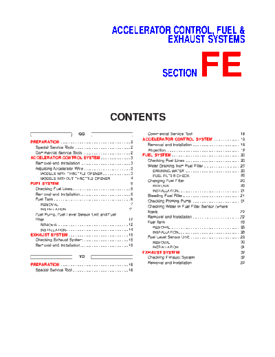
Image preview - the first page of the document
>> Download fe documenatation <<
Text preview - extract from the document
ACCELERATOR CONTROL, FUEL &
EXHAUST SYSTEMS
SECTION FE
CONTENTS
QG Commercial Service Tool...........................................18
ACCELERATOR CONTROL SYSTEM .........................19
PREPARATION ...............................................................2
Removal and Installation ...........................................19
Special Service Tools ..................................................2
Inspection...................................................................19
Commercial Service Tools ...........................................2
FUEL SYSTEM ..............................................................20
ACCELERATOR CONTROL SYSTEM ...........................3
Checking Fuel Lines ..................................................20
Removal and Installation .............................................3
Water Draining from Fuel Filter .................................20
Adjusting Accelerator Wire ..........................................3
DRAINING WATER ..................................................20
MODELS WITH THROTTLE OPENER .........................3
FUEL FILTER CHECK ..............................................20
MODELS WITHOUT THROTTLE OPENER ..................4
Changing Fuel Filter ..................................................20
FUEL SYSTEM ................................................................5
REMOVAL ...............................................................20
Checking Fuel Lines ....................................................5 INSTALLATION........................................................21
Removal and Installation .............................................5 Bleeding Fuel Filter....................................................21
Fuel Tank .....................................................................6 Checking Priming Pump ............................................21
REMOVAL .................................................................7
Checking Water in Fuel Filter Sensor (where
INSTALLATION........................................................11
fitted) ..........................................................................22
Fuel Pump, Fuel Level Sensor Unit and Fuel
Removal and Installation ...........................................22
Filter ...........................................................................12
Fuel Tank ...................................................................23
REMOVAL ...............................................................12
REMOVAL ...............................................................25
INSTALLATION........................................................14
INSTALLATION........................................................28
EXHAUST SYSTEM ......................................................15
Fuel Level Sensor Unit ..............................................29
Checking Exhaust System.........................................15
REMOVAL ...............................................................30
Removal and Installation ...........................................15 INSTALLATION........................................................31
EXHAUST SYSTEM ......................................................32
YD Checking Exhaust System.........................................32
PREPARATION .............................................................18 Removal and Installation ...........................................32
Special Service Tool ..................................................18
PREPARATION QG
Special Service Tools
Special Service Tools NJFE0029
Tool number
Description
Tool name
KV10114400 Loosening or tightening front and rear
Heated oxygen sensor heated oxygen sensors
wrench a: 22 mm (0.87 in)
NT636
KV999G0010 Removing and installing fuel tank lock
Fuel tank lock ring ring
socket
NT057
Commercial Service Tools NJFE0030
Tool number
Description
Tool name
Oxygen sensor thread Reconditioning the exhaust system threads
cleaner before installing a new oxygen sensor (Use
with anti-seize lubricant shown below.)
a: 18 mm dia. with pitch 1.5 mm for zir-
conia oxygen sensor
b: 12 mm dia. with pitch 1.25 mm for
titania oxygen sensor
AEM488
Anti-seize lubricant Lubricating oxygen sensor thread cleaning
(Permatex 133AR or tool when reconditioning exhaust system
equivalent meeting MIL threads
specification MIL-A-
907)
AEM489
FE-2
ACCELERATOR CONTROL SYSTEM QG
Removal and Installation
Removal and Installation NJFE0002
CAUTION:
+ When removing accelerator wire, make a mark to indicate lock nut's initial position.
+ Check that throttle valve opens fully when accelerator pedal is fully depressed. Also check that it
returns to idle position when pedal is released.
+ Check accelerator control parts for improper contact with any adjacent parts.
+ When connecting accelerator wire, be careful not to twist or scratch wire.
YFE006
Adjusting Accelerator Wire NJFE0003
MODELS WITH THROTTLE OPENER NJFE0003S01
1. Remove the vacuum hose connected to the throttle opener.
2. Connect suitable vacuum hose to vacuum pump as shown left.
3. Apply vacuum [more than -40.0 kPa (-400 mbar, -300 mmHg,
-11.81 inHg)] until the throttle drum becomes free from the rod
of the throttle opener.
Make sure that there is clearance between the throttle
drum and rod.
If NG, refer to EC-202, "Basic Inspection".
SEF793WB If OK, go to following step.
FE-3
ACCELERATOR CONTROL SYSTEM QG
Adjusting Accelerator Wire (Cont'd)
4. Loosen lock nut.
5. Tighten accelerator adjusting nut until throttle drum starts to
move.
6. From that position, turn back adjusting nut 1.5 to 2 turns, and
secure lock nut.
7. Release vacuum from the throttle opener.
8. Remove vacuum pump and vacuum hose from the throttle
opener.
9. Reinstall the original vacuum hose to the throttle opener
securely.
SFE248AB
MODELS WITHOUT THROTTLE OPENER NJFE0003S02
1. Loosen lock nut, and tighten adjusting nut until throttle drum
starts to move.
2. From that position turn back adjusting nut 1.5 to 2 turns, and
secure lock nut.
NFE020
FE-4
FUEL SYSTEM QG
Checking Fuel Lines
Checking Fuel Lines NJFE0009
Inspect fuel lines and tank for improper attachment, leaks, cracks,
damage, loose connections, chafing or deterioration.
If necessary, repair or replace faulty parts.
SMA803A
CAUTION:
Tighten high-pressure rubber hose clamp so that clamp end is
3 mm (0.12 in) from hose end.
Tightening torque specifications are the same for all rubber
hose clamps.
Ensure that screw does not contact adjacent parts.
MMA104A
Removal and Installation NJFE0004
WARNING:
When replacing fuel line parts, be sure to observe the following.
+ Put a "CAUTION: FLAMMABLE" sign in workshop.
+ Be sure to furnish workshop with a CO2 fire extinguisher.
+ Do not smoke while servicing fuel system. Keep open flames and sparks away from work area.
CAUTION:
+ Before removing fuel line parts, carry out the following procedures:
a) Put drained fuel in an explosion-proof container and put the lid on securely.
b) Release fuel pressure from fuel line. Refer to EC-40, "Fuel Pressure Release".
c) Disconnect battery ground cable.
+ Always replace O-ring and clamps with new ones.
+ Do not kink or twist tubes when they are being installed.
+ Do not tighten hose clamps excessively to avoid damaging hoses.
+ After installing tubes, run engine and check for fuel leaks at connections.
FE-5
FUEL SYSTEM QG
Fuel Tank
Fuel Tank NJFE0006
JFE607A
FE-6
FUEL SYSTEM QG
Fuel Tank (Cont'd)
SFE649A
REMOVAL NJFE0006S01
For Sedan NJFE0006S0101
1. Release fuel pressure from fuel line.
Refer to EC-40, "Fuel Pressure Release".
2. Disconnect battery ground cable.
3. Open fuel filler lid and filler cap.
4. Drain fuel from fuel tank.
5. Remove rear seat cushion. Refer to BT-60, "Removal and
Installation".
6. Remove inspection hole cover under the rear seat.
JFE613A
FE-7
FUEL SYSTEM QG
Fuel Tank (Cont'd)
7. Disconnect electrical connector.
8. Disconnect the quick connector as follows.
a. Put mating marks on tubes and connectors for correct
installation.
JFE608A
b. Hold the connector while pushing in tabs, and pull out the tube.
CAUTION:
+ The tube can be removed when the tabs are completely
depressed. Do not twist it more than necessary.
+ Do not use any tools to remove the quick connector.
+ Keep the resin tube away from heat. Be especially careful
when welding near the tube.
+ Prevent acid liquid such as battery electrolyte etc. from
getting on the resin tube.
+ Do not bend or twist the tube during installation and
SFE562A removal.
+ Only when the tube is replaced, remove the remaining
retainer.
+ When the tube is replaced, also replace the retainer with
a new one.
Retainer color:
Orange (Feed hose side)
White (Return hose side)
JFE628A
9. Remove exhaust center tube.
10. From rear left area of fuel tank, remove filler hose, vent hose
and EVAP hose.
CAUTION:
To prevent fuel from flowing out, install a blind cap immedi-
ately after the fuel hose is disconnected.
JFE609A
11. Set a suitable transmission jack under fuel tank.
12. Remove fuel tank mounting band bolts while supporting fuel
tank.
JFE610A
FE-8
FUEL SYSTEM QG
Fuel Tank (Cont'd)
13. Lower the fuel tank by 70 to 80 mm (2.76 to 3.15 in), remove
the nuts and clips holding the protector, and then remove the
protector.
+ To remove the clips, use pliers to squeeze the extensions as
shown by the arrows in the figure at left, and then remove the
clip from above.
14. Remove fuel tank.
JFE611A
For Hatchback NJFE0006S0102
1. Disconnect battery ground cable.
2. Open fuel filler lid and filler cap.
3. Drain fuel from fuel tank.
4. Remove rear seat cushion. Refer to BT-60, "Removal and
Installation".
5. Remove inspection hole cover under the rear seat.
JFE613A
6. Disconnect electrical connector.
7. Disconnect the quick connector as follows.
a. Put mating marks on tubes and connectors for correct instal-
lation.
SFE639A
SFE640A
b. Hold the connector while pushing in tabs, and pull out the tube.
CAUTION:
+ The tube can be removed when the tabs are completely
depressed. Do not twist it more than necessary.
+ Do not use any tools to remove the quick connector.
+ Keep the resin tube away from heat. Be especially careful
when welding near the tube.
+ Prevent acid liquid such as battery electrolyte etc. from
getting on the resin tube.
+ Do not bend or twist the tube during installation and
SFE562A removal.
FE-9
FUEL SYSTEM QG
Fuel Tank (Cont'd)
8. From rear left area of fuel tank, remove filler hose, vent hose,
and EVAP hose.
CAUTION:
To prevent fuel from flowing out, install a blind cap immedi-
ately after the fuel hose is disconnected.
SFE650A
9. Remove exhaust center tube.
SFE642A
10. Remove heat insulators from fuel tank side.
SFE643A
11. Set a suitable transmission jack under fuel tank.
12. Remove fuel tank mounting band bolts while supporting fuel
tank.
13. Remove fuel tank.
SFE644A
FE-10
FUEL SYSTEM QG
Fuel Tank (Cont'd)
INSTALLATION NJFE0006S02
To install, reverse the removal procedure. Connect the quick con-
nector as follows:
+ Align mating marks on tubes and connectors for correct instal-
lation.
+ Insert tube into the center of the connector until you hear a
click.
SFE560AA
SFE657A
After connecting quick connector, make sure the connection is
firmly made using the following method.
+ Pull on the fuel tube and connector to make sure they are firmly
connected.
+ Start the engine, increase engine speed and verify that there
are no leaks.
SFE561AA
SFE658A
FE-11
FUEL SYSTEM QG
Fuel Pump, Fuel Level Sensor Unit and Fuel Filter
Fuel Pump, Fuel Level Sensor Unit and Fuel
Filter NJFE0007
SFE671A
REMOVAL NJFE0007S01
For Sedan NJFE0007S0101
1. Release fuel pressure from fuel line.
Refer to EC-40, "Fuel Pressure Release".
2. Disconnect battery ground cable.
3. Open fuel filler lid and filler cap.
4. Remove rear seat cushion. Refer to BT-60, "Removal and
Installation".
5. Remove inspection hole cover under the rear seat.
JFE613A
6. Disconnect electrical connector.
7. Disconnect the quick connectors.
+ For disconnect of quick connectors, refer to step 8. of "Fuel
Tank Removal".
8. Remove the six screws and retainer.
CAUTION:
Use genuine bolts only when fixing retainer.
JFE608A
FE-12
FUEL SYSTEM QG
Fuel Pump, Fuel Level Sensor Unit and Fuel Filter (Cont'd)
9. Pull out the fuel level sensor unit and fuel pump.
+ Do not damage the arm of the fuel level sensor unit and
fuel tank temperature sensor.
SFE564A
10. Remove fuel pump as shown in the figure at left.
+ Put mating marks on fuel pump and fuel filter for correct instal-
lation.
JFE614A
11. Disconnect fuel pump harness connector.
JFE615A
12. Remove fuel filter from fuel level sensor unit as shown in the
figure at left.
+ Put mating marks on fuel filter and fuel level sensor unit for
correct installation.
JFE616A
For Hatchback NJFE0007S0102
1. Disconnect battery ground cable.
2. Open fuel filler lid and filler cap.
3. Remove rear seat cushion. Refer to BT-60, "Removal and
Installation".
4. Remove inspection hole cover under the rear seat.
JFE613A
FE-13
FUEL SYSTEM QG
Fuel Pump, Fuel Level Sensor Unit and Fuel Filter (Cont'd)
5. Disconnect electrical connector.
6. Disconnect the quick connectors.
+ For disconnect of quick connectors, refer to step 7. of "Fuel
Tank Removal".
SFE639A
7. Remove lock ring using a lock ring socket (SST).
SFE376A
8. Pull out the fuel level sensor unit and fuel pump.
+ Do not damage the arm of the fuel level sensor unit and
fuel tank temperature sensor.
INSTALLATION NJFE0007S02
Installation is in reverse order of removal.
SFE648A
FE-14
EXHAUST SYSTEM QG
Checking Exhaust System
Checking Exhaust System NJFE0010
Check exhaust pipes, muffler and mounting for improper
attachment, leaks, cracks, damage, chafing or deterioration.
SMA211A
Removal and Installation NJFE0005
CAUTION:
+ Always replace exhaust gaskets with new ones when
reassembling.
+ With engine running, check all tube connections for
exhaust gas leaks, and entire system for unusual noises.
+ Check to ensure that mounting brackets and mounting
insulators are installed properly and free from undue
stress. Improper installation could result in excessive
noise or vibration.
+ Discard any heated oxygen sensor which has been
dropped from a height of more than 0.5 m (19.7 in) onto a
hard surface such as a concrete floor; use a new one.
+ Before installing a new oxygen sensor, clean exhaust sys-
tem threads using oxygen sensor thread cleaner tool and
apply anti-seize lubricant.
+ Do not overtorque the oxygen sensor. Doing so may
cause damage to the oxygen sensor, resuiting in the MIL
coming on.
+ Be sure to use genuine exhaust system parts which are
designed especially for heat resistance, corrosion
resistance, and shape.
+ Perform the operation with the exhaust system fully
cooled down because the system will be heated just after
the engine stops.
+ Be careful not to cut your hand on the insulator edge.
FE-15
EXHAUST SYSTEM QG
Removal and Installation (Cont'd)
SFE632AA
FE-16
EXHAUST SYSTEM QG
Removal and Installation (Cont'd)
SFE673A
FE-17
PREPARATION YD
Special Service Tool
Special Service Tool NJFE0031
Tool number
Description
Tool name
KV999G0010 Removing and installing fuel tank lock
Fuel tank lock ring ring
socket
NT057
Commercial Service Tool NJFE0027
Tool name Description
Fuel filter wrench Removing fuel filter
a: Max. 100 mm (3.94 in) dia.
NT553
FE-18
ACCELERATOR CONTROL SYSTEM YD
Removal and Installation
Removal and Installation NJFE0013
CAUTION:
+ Do not disassemble the accelerator pedal assembly. Do not remove the sensors and the switches
from the assembly.
+ Avoid impact from dropping etc. during handling.
+ Be careful to keep the assembly away from water.
+ Do not adjust the adjusting screw (painted white) of the accelerator work unit.
+ When the connector of the accelerator sensor is disconnected, reconnect the connector, and touch
"CLEAR" in "OFF ACCEL PO SIG" of the active test using the CONSULT-II. Or, warm up the engine,
then leave it idling for approximately 10 minutes.
SFE629A
Inspection NJFE0020
+ Check that the accelerator pedal moves smoothly within the
whole operation range.
+ Check that the accelerator pedal securely returns to the origi-
nal position.
+ Check that the drum of the accelerator work unit can be fully
opened.
+ Refer to EC-641, "Basic Inspection" for the inspection of the
accelerator work unit and the accelerator pedal switch.
FE-19
FUEL SYSTEM YD
Checking Fuel Lines
Checking Fuel Lines NJFE0019
Inspect fuel lines and tank for improper attachment, leaks, cracks,
damage, chafing and deterioration.
If necessary, repair or replace.
SMA803A
CAUTION:
Tighten high-pressure rubber hose clamp so that clamp end is
3 mm (0.12 in) from hose end.
Tightening torque specifications are the same for all rubber
hose clamps.
Ensure that screw does not contact adjacent parts.
MMA104A
Water Draining from Fuel Filter NJFE0028
DRAINING WATER NJFE0028S01
Open drain valve at the bottom of fuel filter.
FUEL FILTER CHECK NJFE0028S02
Check fuel filter for fuel leakage, damage and other abnormal
sings.
SMA794C
Changing Fuel Filter NJFE0021
REMOVAL NJFE0021S01
1. Take out air duct and upper air cleaner case.
2. Remove connector from water in fuel filter sensor.
3. Remove fuel filter using a fuel filter wrench (commercial ser-
vice tool).
CAUTION:
Do not spill the fuel during removal. If the fuel is spilt, imme-
diately wipe it off. Be especially careful to prevent the fuel
from adhering to the insulators of the engine mounts.
JFE598A
4. Remove water in fuel filter sensor from fuel filter.
FE-20
FUEL SYSTEM YD
Changing Fuel Filter (Cont'd)
INSTALLATION NJFE0021S02
+ Install in the reverse order of removal.
+ Replace the O-ring of the fuel level warning sensor with a new
one.
+ Tighten the fuel filter so that the sealing face contacts the
packing, then retighten it manually by approximately 2/3 turn.
+ After installation, operate the priming pump vertically to per-
form air bleeding.
Refer to FE-22, "Bleeding Fuel Filter".
JFE624A
Bleeding Fuel Filter NJFE0023
1. After the repair, bleed air from the piping by pumping the prim-
ing pump up and down until it becomes heavy.
2. To start the engine, rotate the starter for a maximum of 30
seconds.
To start the engine more quickly, crank the engine while pump-
ing the priming pump (requires two workers).
3. If the engine does not start after rotating the starter for a maxi-
mum of 30 seconds, stop it once, and pump the priming pump
again until it becomes heavy.
4. Rotate the starter again until the engine starts running.
5. After the engine starts, let it idle for at least 1 minute to stabi-
lize the behavior.
+ When air is bled completely, the pumping of the priming
pump suddenly becomes heavy. Stop the operation at that
time.
+ If it is difficult to bleed air by the pumping of the priming
pump (the pumping of the priming pump does not become
heavy), disconnect the fuel supply hose between the fuel
filter and the injection pump. Then, perform the operation
described above, and make sure that fuel comes out. (Use
a pan, etc. so as not to spill fuel. Do not let fuel get on
engine and other parts.) After that, connect the hose, then
bleed air again.
+ Start engine and let it idle for at least one minute after
performing air bleeding.
Checking Priming Pump NJFE0024
Before checking priming pump, make sure that fuel filter is
filled with fuel.
1. Disconnect fuel return hose.
Place a suitable container beneath hose end.
2. Pump priming pump and check that the fuel overflows from the
hose end. If not, replace priming pump.
DEF017
FE-21
FUEL SYSTEM YD
Checking Water in Fuel Filter Sensor (where fitted)
Checking Water in Fuel Filter Sensor (where
fitted) NJFE0025
1. Remove the connector from filter and water in fuel filter sen-
sor.
2. Turn the key switch "ON". Lift the float to ensure that the
warning lamp turns on.
Water in fuel filter sensor tightening torque:
: 3.9 - 5.9 N◦ Jabse Service Manual Search 2026 ◦ Jabse Pravopis ◦ onTap.bg ◦ Other service manual resources online : Fixya ◦ eServiceinfo