Service Manuals, User Guides, Schematic Diagrams or docs for : . Car Manuals Nissan Almera 2000-2003.2006 Approved Nissan Almera 2003 Tino br
<< Back | HomeMost service manuals and schematics are PDF files, so You will need Adobre Acrobat Reader to view : Acrobat Download Some of the files are DjVu format. Readers and resources available here : DjVu Resources
For the compressed files, most common are zip and rar. Please, extract files with Your favorite compression software ( WinZip, WinRAR ... ) before viewing. If a document has multiple parts, You should download all, before extracting.
Good luck. Repair on Your own risk. Make sure You know what You are doing.
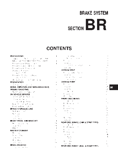
Image preview - the first page of the document
>> Download br documenatation <<
Text preview - extract from the document
BRAKE SYSTEM GI
SECTION BR MA
EM
LC
EC
CONTENTS FE
PRECAUTIONS ...............................................................4 OPERATING CHECK ...............................................19
CL
Supplemental Restraint System (SRS) AIR AIRTIGHT CHECK ...................................................19
BAG and SEAT BELT PRE-TENSIONER...............4 Removal.....................................................................19 MT
Precautions for Brake System.....................................4 Inspection...................................................................19
Precautions When Working On ABS...........................5 OUTPUT ROD LENGTH CHECK ..............................19
Precautions for Brake Control .....................................5 Installation..................................................................20 AT
Diagnosis Precaution...................................................6 VACUUM HOSE.............................................................21
CAN SYSTEM ...........................................................6 Removal and Installation ...........................................21
Precaution for Harness Repair ....................................6 Inspection...................................................................22 AX
CAN SYSTEM ...........................................................6 HOSES AND CONNECTORS ...................................22
Wiring Diagrams and Trouble Diagnosis.....................7 CHECK VALVE ........................................................22
VACUUM PUMP ............................................................23 SU
PREPARATION ...............................................................8
Commercial Service Tools ...........................................8 Removal.....................................................................23
NOISE, VIBRATION AND HARSHNESS (NVH) Installation..................................................................24
TROUBLESHOOTING .....................................................9 Inspection...................................................................24
NVH Troubleshooting Chart.........................................9 Component ................................................................25
ON-VEHICLE SERVICE ................................................10 Disassembly...............................................................25 ST
Checking Brake Fluid Level.......................................10 Assembly ...................................................................25
Checking Brake Line .................................................10 FRONT DISC BRAKE ...................................................27
Changing Brake Fluid ................................................10 Component ................................................................27 RS
Brake Burnishing Procedure......................................10 Pad Replacement ......................................................27
Bleeding Brake System .............................................11 Removal.....................................................................28
Disassembly...............................................................28
BT
BRAKE HYDRAULIC LINE ...........................................12
Hydraulic Circuit.........................................................12 Inspection...................................................................28
Removal.....................................................................12 CALIPER .................................................................28 HA
ROTOR ...................................................................29
Inspection...................................................................12
Assembly ...................................................................30
Installation..................................................................13
BRAKE PEDAL AND BRACKET..................................14
Installation..................................................................30 SC
REAR DISC BRAKE (CAM & STRUT TYPE) ..............31
Removal and Installation ...........................................14
Component ................................................................31
Inspection...................................................................14
Pad Replacement ......................................................31 EL
Adjustment .................................................................14
Removal.....................................................................33
MASTER CYLINDER.....................................................16
Disassembly...............................................................33
Removal.....................................................................16
Inspection...................................................................34
IDX
Disassembly...............................................................16
CALIPER .................................................................34
Inspection...................................................................17
ROTOR ...................................................................35
Assembly ...................................................................17
Assembly ...................................................................35
Installation..................................................................18
Installation..................................................................38
BRAKE BOOSTER........................................................19
REAR DISC BRAKE (BALL & RAMP TYPE) ..............39
On-vehicle Service.....................................................19
CONTENTS (Cont'd)
Component ................................................................39 Basic Inspection 3 ABS Warning Lamp
Pad Replacement ......................................................39 Inspection...................................................................71
Removal.....................................................................41 TROUBLE DIAGNOSES FOR SELF-DIAGNOSTIC
Disassembly...............................................................41 ITEMS.............................................................................72
Inspection...................................................................41 Wheel Sensor System ...............................................72
CALIPER .................................................................41 CAN Communication Lines .......................................73
ROTOR ...................................................................42 ABS Warning Lamp Does Not Illuminate. (ABS
Installation..................................................................42 Warning Lamp Does Not Come on When the
PARKING BRAKE CONTROL ......................................43 Ignition Switch is Turned ON.)...................................73
Components...............................................................43 ABS Warning Lamp Illuminates with Ignition ON,
Removal and Installation ...........................................43 but Does Not Illuminates Off After a Few
Inspection...................................................................43 Seconds. (ABS Warning Lamp has been
Adjustment .................................................................44 Illuminated.) ...............................................................74
TROUBLE DIAGNOSES FOR SYMPTOMS .................75
ABS 1. ABS Works Frequently ..........................................75
2. Unexpected Pedal Action ......................................75
DESCRIPTION ...............................................................45
3. Longer Stopping Distance .....................................76
Purpose......................................................................45
4. ABS Does Not Work..............................................77
ABS (Anti-Lock Brake System) Operation ................45
5. Pedal Vibration and Noise.....................................77
ABS Hydraulic Circuit ................................................45
REMOVAL AND INSTALLATION .................................79
System Components .................................................46
Wheel Sensors ..........................................................79
System Description....................................................46
ABS Actuator and Electric Unit..................................80
SENSOR .................................................................46
REMOVAL ...............................................................80
CONTROL UNIT ......................................................46
INSTALLATION........................................................80
ABS ACTUATOR AND ELECTRIC UNIT ....................46
Sensor Rotor..............................................................81
Component Parts and Harness Connector
REMOVAL ...............................................................81
Location .....................................................................48
INSTALLATION........................................................81
Schematic ..................................................................49
Wiring Diagram - ABS - .............................................50
ESP/TCS/ABS
CAN COMMUNICATION ...............................................53
System Description....................................................53 ON-VEHICLE SERVICE ................................................82
CAN Communication Unit..........................................53 Adjustment of Steering Angle Sensor Neutral
TYPE 1 ...................................................................54 Position ......................................................................82
TYPE 2/TYPE 3 .......................................................56 SYSTEM DESCRIPTION ...............................................84
TYPE 4 ...................................................................58 System Diagram ........................................................84
TYPE 5/TYPE 6 .......................................................60
System Component Parts..........................................85
ON BOARD DIAGNOSTIC SYSTEM
ESP Function.............................................................85
DESCRIPTION ...............................................................61
TCS Function.............................................................86
Trouble Diagnosis Chart by Symptom.......................61
ABS Function.............................................................86
CHECK ITEMS LIST ................................................61
EBD Function.............................................................86
ABS actuator and electric unit Input/Output
Fail-safe Function ......................................................87
Signal Standard .........................................................61
ESP/TCS SYSTEM ..................................................87
SPECIFICATIONS DEFINED BY CONSULT-II ............61
ABS, EBD SYSTEM .................................................87
CONSULT-II Functions ..............................................62
Hydraulic Circuit Diagram..........................................88
CONSULT-II FUNCTION APPLICATION TABLE ..........62
CAN COMMUNICATION ...............................................89
SELF-DIAGNOSIS ...................................................63
System Description....................................................89
DATA MONITOR......................................................66
ACTIVE TEST ..........................................................67 CAN Communication Unit..........................................89
TROUBLE DIAGNOSIS - BASIC INSPECTION ...........70 TYPE 1 ...................................................................90
TYPE 2/TYPE 3 .......................................................92
ABS Actuator and Electric Unit..................................70
TYPE 4 ...................................................................94
Basic Inspection 1 Brake Fluid Level and
TYPE 5/TYPE 6 .......................................................96
Leakage Inspection....................................................70
TROUBLE DIAGNOSIS .................................................97
Basic Inspection 2 Inspection for Loose Power
Supply Terminal .........................................................70
BR-2
CONTENTS (Cont'd)
How to Perform Trouble Diagnosis for Quick and Inspection 12 When ST ANG SEN SIGNAL GI
Accurate Repair .........................................................97 Appears on Self-diagnostic Results Display ...........140
INTRODUCTION ......................................................97 Inspection 13 CAN Communication System ...........140
DIAGNOSIS FLOWCHART .......................................98 Inspection 14 When ESTM VEH SPD SIG MA
ASKING COMPLAINTS ............................................99 Appears on Self-diagnostic Results Display ...........142
EXAMPLE OF DIAGNOSIS SHEET ...........................99 Inspection 15 ESP OFF Indicator Lamp Does
Component Parts Location ......................................100 Not Illuminate...........................................................142
EM
Schematic ................................................................101 Component Inspection.............................................142
Wiring Diagram - ESP/TCS/ABS - ..........................102 ESP OFF SWITCH .................................................142
Control Unit Input/Output Signal Standard..............107
LC
Symptom 1 Excessive ABS Function Operation
REFERENCE VALUE FROM CONSULT-II ................107 Frequency ................................................................143
CONSULT-II Functions ............................................110 Symptom 2 Unexpected Pedal Reaction ................143 EC
CONSULT-II FUNCTION APPLICATION TABLE
Symptom 3 The Braking Distance Is Long .............144
(MAIN ITEMS) .......................................................110
Symptom 4 ABS Function Does Not Operate.........145
CONSULT-II BASIC OPERATION PROCEDURE ...... 111 FE
Symptom 5 Pedal Vibration or ABS Operation
SELF-DIAGNOSIS .................................................112
DATA MONITOR....................................................115 Sound Occurs ..........................................................145
ACTIVE TEST ........................................................118 Symptom 6 Vehicle Jerks During ESP/TCS/ABS
CL
For Fast and Accurate Diagnosis ............................120 Control .....................................................................147
PRECAUTIONS FOR DIAGNOSIS ..........................120 WHEEL SENSORS......................................................149
Basic Inspection.......................................................122 Removal and Installation .........................................149 MT
BASIC INSPECTION 1 BRAKE FLUID LEVEL, REMOVAL .............................................................149
LEAKS, AND BRAKE PADS ...................................122 INSTALLATION......................................................149
BASIC INSPECTION 2 POWER SYSTEM SENSOR ROTOR ........................................................150 AT
TERMINAL LOOSENESS AND BATTERY Removal and Installation .........................................150
INSPECTION .........................................................122 REMOVAL .............................................................150
BASIC INSPECTION 3 ABS WARNING LAMP, INSTALLATION......................................................150 AX
ESP OFF INDICATOR LAMP, SLIP INDICATOR ACTUATOR AND ELECTRIC UNIT (ASSEMBLY) ....151
LAMP INSPECTION ...............................................122 Removal and Installation .........................................151
Inspection 1 Wheel Sensor System ........................123 G SENSOR ..................................................................152
SU
Inspection 2 Engine System....................................126 Removal and Installation .........................................152
Inspection 3 ESP/TCS/ABS Control Unit System ...127 REMOVAL .............................................................152
Inspection 4 Pressure Sensor System ....................127 INSTALLATION......................................................152
Inspection 5 Steering Angle Sensor System...........129 STEERING ANGLE SENSOR .....................................153
Inspection 6 Yaw Rate/Side G sensor System .......130 Removal and Installation .........................................153 ST
Inspection 7 Solenoid and ESP Change-over
Valve System ...........................................................132 SERVICE DATA AND SPECIFICATIONS (SDS) .......154
Inspection 8 Actuator Motor, Motor Relay, and General Specifications.............................................154 RS
Circuit.......................................................................134 Disc Brake ...............................................................154
Inspection 9 ABS Actuator and Electric Unit Brake Pedal .............................................................154
(Control Unit) Power Supply and Ground Circuit ....136 Parking Brake ..........................................................154
BT
Inspection 10 Stop Lamp Switch System................138
Inspection 11 Brake Fluid Level Sensor System ....139 HA
SC
EL
IDX
BR-3
PRECAUTIONS
Supplemental Restraint System (SRS) "AIR BAG" and "SEAT BELT PRE-TENSIONER"
Supplemental Restraint System (SRS) "AIR
BAG" and "SEAT BELT PRE-TENSIONER" NLBR0081
The Supplemental Restraint System such as "AIR BAG" and "SEAT BELT PRE-TENSIONER" used along with
a seat belt, helps to reduce the risk or severity of injury to the driver and front passenger for certain types of
collision. The SRS system composition which is available to NISSAN MODEL V10 is as follows (The compo-
sition varies according to the destination and optional equipment.):
◦ Jabse Service Manual Search 2026 ◦ Jabse Pravopis ◦ onTap.bg ◦ Other service manual resources online : Fixya ◦ eServiceinfo