Service Manuals, User Guides, Schematic Diagrams or docs for : . Car Manuals Nissan Almera 2000-2003.2006 Approved Nissan Almera 2003 Tino sc
<< Back | HomeMost service manuals and schematics are PDF files, so You will need Adobre Acrobat Reader to view : Acrobat Download Some of the files are DjVu format. Readers and resources available here : DjVu Resources
For the compressed files, most common are zip and rar. Please, extract files with Your favorite compression software ( WinZip, WinRAR ... ) before viewing. If a document has multiple parts, You should download all, before extracting.
Good luck. Repair on Your own risk. Make sure You know what You are doing.
Image preview - the first page of the document
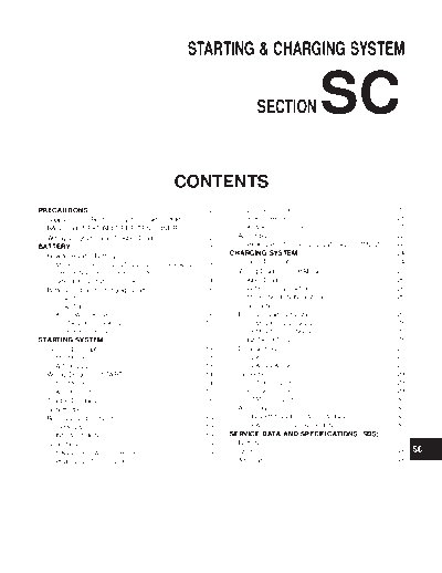
>> Download sc documenatation <<
Text preview - extract from the document
                                                                     STARTING & CHARGING SYSTEM                                                                            GI


                                                                                                 SECTION                       SC                                          MA

                                                                                                                                                                           EM

                                                                                                                                                                           LC

                                                                                                                                                                           EC

                                                              CONTENTS                                                                                                     FE


PRECAUTIONS ...............................................................2                BRUSH CHECK .......................................................20
                                                                                                                                                                           CL
  Supplemental Restraint System (SRS) AIR                                                   YOKE CHECK .........................................................21
  BAG and SEAT BELT PRE-TENSIONER...............2                                           ARMATURE CHECK ................................................21
                                                                                                                                                                           MT
  Wiring Diagrams and Trouble Diagnoses....................2                          Assembly ...................................................................22
BATTERY.........................................................................3        PINION PROTRUSION LENGTH ADJUSTMENT ........22
  How to Handle Battery ................................................3           CHARGING SYSTEM ....................................................24                 AT
     METHODS OF PREVENTING OVER-DISCHARGE ......3                                     System Description....................................................24
     CHECKING ELECTROLYTE LEVEL ............................3                         Wiring Diagram - CHARGE -.....................................25
     SPECIFIC GRAVITY CHECK ......................................4                   Trouble Diagnoses.....................................................26             AX
  Battery Test and Charging Chart.................................6                      WITH IC REGULATOR .............................................26
     CHART I ...................................................................6        MALFUNCTION INDICATOR ....................................26
     CHART II ..................................................................7     Construction...............................................................27        SU
     A: SLOW CHARGE ....................................................8             Removal and Installation ...........................................28
     B: STANDARD CHARGE ..........................................10                     REMOVAL (QG ENGINE) .........................................28
     C: QUICK CHARGE .................................................11                 REMOVAL (YD ENGINE)..........................................28
                                                                                                                                                                           BR
STARTING SYSTEM .....................................................13                  INSTALLATION........................................................28
  System Description....................................................13            Disassembly...............................................................28
                                                                                                                                                                           ST
     M/T MODELS ..........................................................13             REAR COVER .........................................................28
     A/T MODELS ...........................................................13            REAR BEARING ......................................................28
  Wiring Diagram - START -.........................................14                 Inspection...................................................................29      RS
     M/T MODELS ..........................................................14             ROTOR CHECK ......................................................29
     A/T MODELS ...........................................................15            BRUSH CHECK .......................................................29
  Trouble Diagnoses.....................................................16               STATOR CHECK .....................................................30              BT
  Construction...............................................................17       Assembly ...................................................................30
  Removal and Installation ...........................................19                 RING FITTING IN REAR BEARING ...........................30
     REMOVAL ...............................................................19           REAR COVER INSTALLATION .................................30                       HA
     INSTALLATION........................................................19         SERVICE DATA AND SPECIFICATIONS (SDS) .........31
  Inspection...................................................................19     Battery........................................................................31
     MAGNETIC SWITCH CHECK ...................................19                      Starter ........................................................................31
     PINION/CLUTCH CHECK .........................................20                  Alternator ...................................................................31

                                                                                                                                                                           EL

                                                                                                                                                                           IDX
                                             PRECAUTIONS
Supplemental Restraint System (SRS) "AIR BAG" and "SEAT BELT PRE-TENSIONER"

                                            Supplemental Restraint System (SRS) "AIR
                                            BAG" and "SEAT BELT PRE-TENSIONER"                              NLSC0001
The Supplemental Restraint System such as "AIR BAG" and "SEAT BELT PRE-TENSIONER" used along with
a seat belt, helps to reduce the risk or severity of injury to the driver and front passenger for certain types of
collision. The SRS system composition which is available to NISSAN MODEL V10 is as follows (The compo-
sition varies according to the destination and optional equipment.):
◦ Jabse Service Manual Search 2026 ◦ Jabse Pravopis ◦ onTap.bg ◦ Other service manual resources online : Fixya ◦ eServiceinfo