Service Manuals, User Guides, Schematic Diagrams or docs for : . Car Manuals Nissan Almera 2000-2003.2006 Approved Nissan Almera 2006 Classic B10 AT
<< Back | HomeMost service manuals and schematics are PDF files, so You will need Adobre Acrobat Reader to view : Acrobat Download Some of the files are DjVu format. Readers and resources available here : DjVu Resources
For the compressed files, most common are zip and rar. Please, extract files with Your favorite compression software ( WinZip, WinRAR ... ) before viewing. If a document has multiple parts, You should download all, before extracting.
Good luck. Repair on Your own risk. Make sure You know what You are doing.
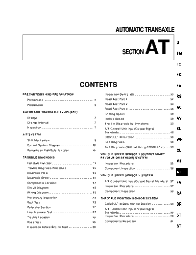
Image preview - the first page of the document

>> Download AT documenatation <<
Text preview - extract from the document
                                                                                                      AUTOMATIC TRANSAXLE


                                                                                                              SECTION                   AT
                                                                 CONTENTS
PRECAUTIONS AND PREPARATION                                                               Inspection During Idle .............................................. 30

  Precautions .................................................................. 5        Road Test Part 1 ....................................................... 32

  Preparation ................................................................... 5       Road Test Part 2 ....................................................... 34
                                                                                          Road Test Part 3 ....................................................... 36
AUTOMATIC TRANSAXLE FLUID (ATF)
                                                                                          Shifting Speed ........................................................... 38
  Change .......................................................................... 7     Lockup Speed ............................................................ 38
  Change Interval ........................................................... 7           Trouble Diagnosis by Symptoms ........................... 39
  Inspection ..................................................................... 7      A/T Control Unit Input/Output Signal
                                                                                          Standards ................................................................... 48
A/T SYSTEM
                                                                                          CONSULT-II Function ............................................... 50
  Shift Mechanism .......................................................... 9
                                                                                          Self-Diagnosis ........................................................... 50
  Control System Diagram ......................................... 10
                                                                                          Self-Diagnosis (Without Using CONSULT-II) ...... 53
  Remarks on Fail-Safe Function .............................. 10
                                                                                        VEHICLE SPEED SENSOR 1 (OUTPUT SHAFT
TROUBLE DIAGNOSIS                                                                       REVOLUTION SENSOR) SYSTEM
  Fail-Safe Function ..................................................... 11             Inspection Procedure ................................................ 55
  Trouble Diagnosis Procedure .................................. 12                       Component Inspection ............................................. 56
  Diagnosis Flow .......................................................... 13
                                                                                        VEHICLE SPEED SENSOR 2 SYSTEM
  Diagnosis Sheet ........................................................ 14
                                                                                          A/T Control Unit Input/Output Signal Standard .. 57
  Components Location .............................................. 17
                                                                                          Inspection Procedure ................................................ 57
  Circuit Diagram ......................................................... 18
                                                                                          Component Inspection ............................................. 58
  Wiring Diagram ......................................................... 19
  Preliminary Inspection ............................................. 25               THROTTLE POSITION SENSOR SYSTEM
  Stall Test ..................................................................... 25
                                                                                          CONSULT-II Data Monitor Display ........................ 59
  Defective Section ...................................................... 27
                                                                                          A/T Control Unit Input/Output Signal
  Line Pressure Test .................................................... 27              Standards ................................................................... 59
  Trouble Location ........................................................ 29            Inspection Procedure ................................................ 59

  Road Test .................................................................... 29       Components Inspection ........................................... 61

  Inspection before Engine Start ............................... 30
                                                               CONTENTS
SHIFT SOLENOID A SYSTEM                                                              INHIBITOR SWITCH, O/D SWITCH, IDLE SWITCH
                                                                                     AND FULL SWITCH SYSTEMS
  A/T Control Unit Input/Output Signal
  Standards ................................................................... 63     Inspection Procedure ................................................ 79
  Inspection Procedure ................................................ 63             Component Inspection ............................................. 82
  Component Inspection ............................................. 64
                                                                                     TROUBLE DIAGNOSIS BY SYMPTOMS
SHIFT SOLENOID B SYSTEM                                                                A/T CHECK Indicator Light does not Turn ON .... 84
  A/T Control Unit Input/Output Signal                                                 Engine does not Start in P and N Ranges ........... 85
  Standards ................................................................... 65     The Vehicle Moves in P Range when Pushed ...... 86
  Inspection Procedure ................................................ 65             The Vehicle Drives in N Range ............................... 86
  Component Inspection ............................................. 66                Too much Shift Shock when Shifting from N to R
                                                                                       Range .......................................................................... 88
OVERRUN CLUTCH SOLENOID SYSTEM
                                                                                       The Vehicle cannot Drive in R Range or
  A/T Control Unit Input/Output Signal                                                 Extremely Bad Acceleration .................................... 89
  Standards ................................................................... 67     The Vehicle cannot Drive in D, 3, 2, 1 Range or
  Inspection Procedure ................................................ 67             Extremely Bad Acceleration .................................... 91

  Component Inspection ............................................. 68                The Vehicle does not Start from D1 ...................... 93
                                                                                       Does not Shift from D1 to D2 in D Range.
LOCKUP SOLENOID SYSTEM                                                                 Does not Kickdown from D4 to D2 ......................... 96
  CONSULT-II Data Monitor Display ........................ 69                          Does not Shift from D2 to D3 in D Range ............ 98
  A/T Control Unit Input/Output Signal                                                 Does not Shift from D3 to D4 in D Range .......... 101
  Standards ................................................................... 69     Does not Lockup ..................................................... 103
  Inspection Procedure ................................................ 69             Does not Maintain the Lockup State ................... 104
  Component Inspection ............................................. 70                Lockup does not Release ...................................... 105

FLUID PRESSURE SENSOR SYSTEM AND A/T                                                   Engine Speed does not Drop to Idle RPM
CONTROL UNIT POWER SYSTEM                                                              when Decelerating in D Range (D4  D3) ......... 106
                                                                                       Does not Shift from D4 to D3 in D Range under
  CONSULT-II Data Monitor Display ........................ 71
                                                                                       When Shifted from D to 3 ...................................... 108
  A/T Control Unit Input/Output Signal
                                                                                       Does not Shift from D3 to 2 2 when Selector
  Standards ................................................................... 71
                                                                                       Lever is Moved from D Range to 2 Range ......... 109
  Inspection Procedure ................................................ 71
                                                                                       Does not Shift from 2 2 to 1 1 when Selector
  Component Inspection ............................................. 73                Lever is Moved from 2 Range to 1 Range .......... 109
                                                                                       No Engine Brake in "1" Range .............................. 110
ENGINE CIRCUIT SIGNAL SYSTEM
                                                                                       Cannot do Self-Diagnosis ...................................... 110
  Inspection Procedure ................................................ 74
                                                                                       A/T Shift Lock does not Work Properly .............. 115
LINE PRESSURE SOLENOID SYSTEM
                                                                                     SHIFT CONTROL SYSTEM
  CONSULT-II Data Monitor Display ........................ 76
                                                                                       Shift Control System .............................................. 119
  A/T Control Unit Input/Output Signal
                                                                                       Removal
◦ Jabse Service Manual Search 2024 ◦ Jabse Pravopis ◦ onTap.bg ◦ Other service manual resources online : Fixya ◦ eServiceinfo