Service Manuals, User Guides, Schematic Diagrams or docs for : . Car Manuals Nissan Almera 2000-2003.2006 Approved Nissan Almera 2006 Classic B10 WH
<< Back | HomeMost service manuals and schematics are PDF files, so You will need Adobre Acrobat Reader to view : Acrobat Download Some of the files are DjVu format. Readers and resources available here : DjVu Resources
For the compressed files, most common are zip and rar. Please, extract files with Your favorite compression software ( WinZip, WinRAR ... ) before viewing. If a document has multiple parts, You should download all, before extracting.
Good luck. Repair on Your own risk. Make sure You know what You are doing.
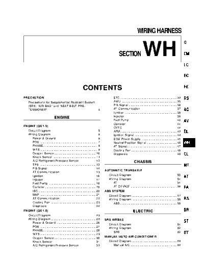
Image preview - the first page of the document

>> Download WH documenatation <<
Text preview - extract from the document
                                                                                                                           WIRING HARNESS


                                                                                                     SECTION                     WH
                                                                 CONTENTS
PRECAUTION                                                                                     ETC ........................................................................ 33
  Precautions for Supplemental Restraint System                                                AWU ....................................................................... 35
  (SRS) "AIR BAG" and "SEAT BELT PRE-                                                          P.S Signal ............................................................. 36
  TENSIONER" ............................................................... 4                 AT Communication .............................................. 37
                                                                                               Ignition .................................................................. 38
                                ENGINE                                                         Injector .................................................................. 39
                                                                                               Fuel Pump ............................................................. 40
                                                                                               Canister ................................................................. 41
ENGINE (QG1.5)
                                                                                               CVTC ..................................................................... 42
  Circuit Diagram ........................................................... 5                AFM ........................................................................ 43
  Wiring Diagram ........................................................... 6                 Ignition Signal ...................................................... 44
     Power & Ground .................................................... 6                     ECM Power Supply ............................................. 45
     POS .......................................................................... 7          Neutral Position Signal ...................................... 46
     PHASE ..................................................................... 8             AT Signal ............................................................... 47
     WTS ......................................................................... 9           Cooling Fan .......................................................... 48
     Oxygen Sensor ..................................................... 10                    Diagnosis .............................................................. 49
     Knock Sensor ....................................................... 11
     A/C Refrigerant Pressure Sensor ..................... 12                                                          CHASSIS
     TPS ........................................................................ 13
     P.S Signal ............................................................. 14
                                                                                        AUTOMATIC TRANSAXLE
     AT Communication .............................................. 15
     Ignition .................................................................. 16       Circuit Diagram ......................................................... 50
     Injector .................................................................. 17       Wiring Diagram ......................................................... 51
     Fuel Pump ............................................................. 18              AT ........................................................................... 51
     Canister ................................................................. 19           AT-DEVICE ........................................................... 56
     ISC ......................................................................... 20   ABS SYSTEM
     MAP ........................................................................ 21      Circuit Diagram ......................................................... 57
     AT Communication .............................................. 22                   Wiring Diagram ......................................................... 58
     Cooling Fan .......................................................... 23               ABS ........................................................................ 58
     Diagnosis .............................................................. 24
ENGINE (QG1.6)                                                                                                       ELECTRIC
  Circuit Diagram ......................................................... 25
  Wiring Diagram ......................................................... 26           SRS AIRBAG
     Power & Ground .................................................. 26
                                                                                          Circuit Diagram ......................................................... 61
     POS ........................................................................ 27
                                                                                          Wiring Diagram ......................................................... 62
     PHASE ................................................................... 28
                                                                                             SRS ........................................................................ 62
     WTS ....................................................................... 29
     Oxygen Sensor ..................................................... 30             MANUAL/AUTO AIR CONDITIONER
     Knock Sensor ....................................................... 31              Circuit Diagram ......................................................... 64
     A/C Refrigerant Pressure Sensor ..................... 32                                Manual A/C ........................................................... 64
                                                                CONTENTS
  Wiring Diagram ......................................................... 65                 Headlamp ............................................................ 117
     Manual A/C ........................................................... 65                Headlamp Aiming .............................................. 118
  Circuit Diagram ......................................................... 70         TAIL LAMP
     Auto A/C ................................................................ 70
                                                                                         Circuit Diagram ....................................................... 119
  Wiring Diagram ......................................................... 71
                                                                                         Wiring Diagram ....................................................... 120
     Auto A/C ................................................................ 71
                                                                                            Tail lamp .............................................................. 120
AUDIO
                                                                                       FOG LAMP
  Circuit Diagram ......................................................... 77
                                                                                         Wiring Diagram ....................................................... 122
     Audio ...................................................................... 77
                                                                                            Fog lamp (FR) .................................................... 122
  Wiring Diagram ......................................................... 78
                                                                                            Fog lamp (RR) ................................................... 123
     Audio ...................................................................... 78
                                                                                       ROOM LAMP
COMBINATION METER
                                                                                         Wiring Diagram ....................................................... 124
  Circuit Diagram ......................................................... 80
                                                                                            Room lamp ......................................................... 124
  Wiring Diagram ......................................................... 81
     Warning light ........................................................ 81         TRUNK ROOM LAMP
     Gage ...................................................................... 85      Wiring Diagram ....................................................... 125
COMBINATION METER - CHIME                                                                   Trunk room lamp ............................................... 125

  Circuit Diagram ......................................................... 87         STOP LAMP
  Wiring Diagram ......................................................... 88            Wiring Diagram ....................................................... 126
     Warning light (Buzzer) ........................................ 88                     Stop lamp ............................................................ 126
     Meter ...................................................................... 90   REVERSE LAMP
     Meter (Diagnosis) ................................................ 91
                                                                                         Wiring Diagram ....................................................... 127
LOCK
◦ Jabse Service Manual Search 2024 ◦ Jabse Pravopis ◦ onTap.bg ◦ Other service manual resources online : Fixya ◦ eServiceinfo