Service Manuals, User Guides, Schematic Diagrams or docs for : . Car Manuals Nissan Altima 2000-2005 Approved Nissan Altima 2000 bt
<< Back | HomeMost service manuals and schematics are PDF files, so You will need Adobre Acrobat Reader to view : Acrobat Download Some of the files are DjVu format. Readers and resources available here : DjVu Resources
For the compressed files, most common are zip and rar. Please, extract files with Your favorite compression software ( WinZip, WinRAR ... ) before viewing. If a document has multiple parts, You should download all, before extracting.
Good luck. Repair on Your own risk. Make sure You know what You are doing.
Image preview - the first page of the document
>> Download bt documenatation <<
Text preview - extract from the document
BODY & TRIM
BT
GI
SECTION MA
EM
LC
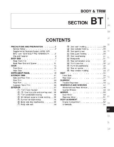
CONTENTS
EC
PRECAUTIONS AND PREPARATION....................... 2 8Door sash molding................................. 29
Service Notice......................................................... 2 9 Door outside molding............................. 30
Supplemental Restraint System (SRS) ``AIR 10 Door parting seal ................................... 30 FE
BAG'' and ``SEAT BELT PRE-TENSIONER''.......... 2 11 Side guard molding................................ 30
Clip and Fastener ................................................... 3 12 Door weatherstrip .................................. 31
BODY END ................................................................. 7 13 Mudguards ............................................. 31
CL
Body Front End....................................................... 7 14 Rear combination lamp.......................... 32
Body Rear End and Opener ................................. 11 15 Front tower bar ...................................... 32
MT
DOOR........................................................................ 15 16 Trunk lid weatherstrip ............................ 32
Front Door............................................................. 15 17 Rear air spoiler ...................................... 33
Rear Door ............................................................. 17 18 Rear window molding ............................ 33 AT
INSTRUMENT PANEL.............................................. 18 SEAT ......................................................................... 34
INTERIOR TRIM ....................................................... 21 Front Seat ............................................................. 35
Side and Floor Trim .............................................. 21 Rear Seat.............................................................. 37 FA
Door Trim .............................................................. 23 SUNROOF................................................................. 39
Roof Trim .............................................................. 25 Trouble Diagnoses ................................................ 43 RA
Luggage Room Trim ............................................. 26 WINDSHIELD AND WINDOWS ............................... 47
EXTERIOR ................................................................ 27 Windshield and Rear Window .............................. 48
1 Front hood insulator............................... 28 Quarter Window .................................................... 49 BR
2 , 3 Cowl top grille and cowl top seal.... 28 MIRROR .................................................................... 50
4 Front windshield molding....................... 28 Door Mirror............................................................ 50
4 Windshield upper and side molding ...... 28 Rearview Mirror..................................................... 51 ST
5 Sunroof lid weatherstrip......................... 29 BODY ALIGNMENT.................................................. 52
6 Body side drip weatherstrip ................... 29 Engine Compartment ............................................ 52
RS
7 Body side welt ....................................... 29 Underbody............................................................. 54
BT
HA
EL
IDX
PRECAUTIONS AND PREPARATION
Service Notice
q When removing or installing various parts, place a cloth or padding on the vehicle body to prevent
scratches.
q Handle trim, molding, instruments, grille, etc. carefully during removal or installation. Be careful not
to soil or damage them.
q Apply sealing compound where necessary when installing parts.
q When applying sealing compound, be careful that the sealing compound does not protrude from parts.
q When replacing any metal parts (for example body outer panel, members, etc.), be sure to take rust
prevention measures.
Supplemental Restraint System (SRS) ``AIR
BAG'' and ``SEAT BELT PRE-TENSIONER''
The Supplemental Restraint System such as ``AIR BAG'' and ``SEAT BELT PRE-TENSIONER'' used along
with a seat belt, helps to reduce the risk or severity of injury to the driver and front passenger for certain
types of collision. The SRS composition which is available to NISSAN MODEL L30 is as follows (The
composition varies according to the destination and optional equipment.):
q For a frontal collision
The Supplemental Restraint System consists of driver air bag module (located in the center of the
steering wheel), front passenger air bag module (located on the instrument panel on passenger side),
seat belt pre-tensioners, a diagnosis sensor unit, warning lamp, wiring harness and spiral cable.
q For a side collision
The Supplemental Restraint System consists of front side air bag module (located in the outer side
of front seat), satellite sensor, diagnosis sensor unit (one of components of air bags for a frontal
collision), wiring harness, warning lamp (one of components of air bags for a frontal collision).
Information necessary to service the system safely is included in the RS section of this service
manual.
WARNING:
q To avoid rendering the SRS inoperative, which could increase the risk of personal injury or
death in the event of a collision which would result in air bag inflation, all maintenance should
be performed by an authorized NISSAN dealer. For removal of Spiral cable and Air Bag Module,
see the RS section.
q Improper maintenance, including incorrect removal and installation of the SRS, can lead to
personal injury caused by unintentional activation of the system.
q Do not use electrical test equipment on any circuit related to the SRS unless instructed to in
this Service Manual. Spiral cable and wiring harnesses (except ``SEAT BELT PRE-TEN-
SIONER'') covered with yellow insulation either just before the harness connectors or for the
complete harness are related to the SRS.
BT-2
PRECAUTIONS AND PREPARATION
Clip and Fastener
q Clips and fasteners in BT section correspond to the following numbers and symbols.
q Replace any clips and/or fasteners which are damaged during removal or installation. GI
Symbol
Shapes Removal & Installation
No.
MA
EM
C101
LC
SBF302H SBF367B EC
FE
C103
CL
MT
SBT095 SBF423H
AT
FA
C203
RA
BR
SBF258G SBF708E
ST
C205
RS
BT
MBT080A WBT033 HA
EL
IDX
BT-3
PRECAUTIONS AND PREPARATION
Clip and Fastener (Cont'd)
Symbol
Shapes Removal & Installation
No.
C206
MBF519B MBF520B
CE103
SBF104B SBF147B
CF118
SBF151D SBF259G
CG101
SBF145B SBF085B
CR103
SBF768B SBF770B
BT-4
PRECAUTIONS AND PREPARATION
Clip and Fastener (Cont'd)
Symbol
Shapes Removal & Installation
No.
GI
MA
CS101
EM
LC
SBF078B ASBF140B
EC
FE
CL
MT
AT
FA
RA
BR
ST
RS
BT
HA
EL
IDX
BT-5
PRECAUTIONS AND PREPARATION
NOTES
BT-6
BODY END
Body Front End
q When removing or installing hood, place a cloth or other padding on front fender panels and cowl top.
This prevents vehicle body from being scratched. GI
q Bumper fascia is made of plastic. Do not use excessive force and keep oil away from it.
q Hood adjustment: Adjust at hinge portion.
q Hood lock adjustment: After adjusting, check hood lock control operation. Apply a coat of grease to MA
engaging mechanism of hood lock.
q Hood opener: Do not attempt to bend cable forcibly. Doing so increases effort required to unlock
hood. EM
REMOVAL -- Front bumper assembly
1 Remove screws and clips securing bumper fascia to left and right front fender protectors. , LC
2 Remove bolts securing bumper fascia to engine undercover.
3 Remove bolts securing bumper fascia to bumper reinforcement and fascia support.
EC
4 Remove bumper fascia and energy absorber from vehicle.
5 Remove fog lamp from bumper reinforcement.
6 Remove bumper reinforcement bolts and bumper reinforcement. FE
7 Remove bumper stay bolts and bumper stays.
CL
MT
AT
FA
RA
BR
ST
RS
BT
HA
EL
IDX
BT-7
BODY END
Body Front End (Cont'd)
WBT005
BT-8
BODY END
Body Front End (Cont'd)
GI
MA
EM
LC
EC
FE
CL
MT
AT
FA
RA
BR
ST
RS
BT
HA
EL
IDX
WBT006
BT-9
BODY END
NOTES
BT-10
BODY END
Body Rear End and Opener
q When removing or installing trunk lid, place a cloth or other padding on rear fender panels. This pre-
vents vehicle body from being scratched. GI
q Bumper fascia is made of plastic. Do not use excessive force and be sure to keep oil away from it.
q Trunk lid adjustment: Adjust at hinge-trunk lid portion for proper trunk lid fit.
q Trunk lid lock system adjustment: Adjust striker so that it is in the center of the lock. After adjustment, MA
check trunk lid lock operation.
q Opener cable: Do not attempt to bend cable forcibly.
q After installation, make sure that trunk lid and fuel filler lid open smoothly. EM
REMOVAL -- Rear bumper assembly
1 Remove screws securing bumper fascia to rear fender. LC
2 Remove clips securing bumper fascia to rear fender.
3 Remove clips securing bumper fascia to bumper reinforcement.
EC
Disconnect the license plate lamp electrical connectors.
4 Remove clips securing bumper fascia to rear panel.
5 Remove bumper fascia and energy absorber from vehicle. FE
6 Remove both parts of bumper reinforcement from bumper stays.
7 Reposition trunk floor carpet to access trunk floor.
8 Remove plugs from floor and then remove bumper stay mount bolts. CL
9 Remove bumper stays from vehicle.
MT
AT
FA
RA
BR
ST
RS
BT
HA
EL
IDX
BT-11
BODY END
Body Rear End and Opener (Cont'd)
WBT007
BT-12
BODY END
Body Rear End and Opener (Cont'd)
GI
MA
EM
LC
EC
FE
CL
MT
AT
FA
RA
BR
ST
RS
BT
HA
EL
IDX
WBT012
BT-13
BODY END
Body Rear End and Opener (Cont'd)
WBT013
BT-14
DOOR
q For removal of door trim, refer to ``Door Trim'', (BT-23).
q When removing door, be sure not to scratch vehicle body.
q After adjusting door or door lock, check door lock operation.
q When disassembling rear door window, it is better to remove upper and waist roller mounting first. GI
Front Door MA
EM
LC
EC
FE
CL
MT
AT
FA
RA
BR
ST
RS
BT
HA
EL
IDX
WBT066
BT-15
DOOR
Front Door (Cont'd)
q Remove the inside ``Door Trim'', (BT-23).
q Remove the inside door plastic vapor barrier.
q Remove the window glass.
q Remove the acorn nut and bolts that attach the window run rubber assembly.
q Remove the window run rubber assembly.
ABT407
BT-16
DOOR
Rear Door
GI
MA
EM
LC
EC
FE
CL
MT
AT
FA
RA
BR
ST
RS
BT
HA
EL
IDX
WBT067
BT-17
INSTRUMENT PANEL
CAUTION:
q Disconnect both terminals from battery in advance.
q Disconnect air bag module connectors in advance.
q Never tamper with or force air bag lid open, as this may adversely affect air bag performance.
q Be careful not to scratch finishers and other parts.
q Wrap the tip of a flat-bladed screwdriver with a cloth when removing metal clips from gar-
nishes.
REMOVAL -- Instrument panel assembly
Instrument panel assembly Combination meter Instrument panel center console A/C & heater control Audio
1 Remove kick plate and dash side finisher on driver side. Refer to BT-21.
2 Instrument lower panel on driver side
q Remove two screws.
3 Dash lower reinforcement panel
q Remove two screws.
4 Remove steering column mounting nuts. Refer to ``Steering
Wheel and Steering Column'' for details.
5 Cluster lid A
qRemove two screws, then disconnect harness connectors.
6 Combination meter
Remove four screws, then disconnect harness connectors.
7 Glove box assembly
q Remove five screws.
8 Remove passenger side air bag module. Refer to RS section.
9 Instrument lower covers.
10 A/T finisher or M/T boot
q Snaps in and out of place.
11 Cluster lid C
q Remove four screws.
12 Audio and deck pocket
q Remove four screws.
13 A/C & heater control
q Remove four screws.
14 Center console assembly
q Remove five screws.
15 Instrument center panel
q Remove two screws.
16 Front defroster grilles.
17 Front pillar garnish
q Refer to BT-21.
18 Switch panel.
19 Instrument panel assembly
q Remove three nuts and four
screws.
20 Instrument stay assemblies, if
necessary
q Remove eight nuts.
21 Steering member assembly, if
necessary
q Remove five nuts and one bolt.
BT-18
INSTRUMENT PANEL
GI
MA
EM
LC
EC
FE
CL
MT
AT
FA
RA
BR
ST
RS
BT
HA
EL
IDX
WBT002
BT-19
INSTRUMENT PANEL
WBT034
BT-20
INTERIOR TRIM
CAUTION: Side and Floor Trim
Wrap the tip of flat-bladed screwdriver with a cloth when removing metal clips from garnishes.
REMOVAL -- Body side trim GI
Remove front and rear seats and seatbelts.
1 Remove front and rear kick plates.
2 Remove dash side finisher. MA
3 Remove center pillar lower garnish.
4 Remove front and rear body side welts.
5 Remove center pillar upper garnish. EM
6 Remove front pillar garnish.
7 Remove rear pillar garnish.
8 Remove center high mount stop lamp. LC
9 Remove rear seat finisher.
10 Remove rear parcel shelf.
EC
FE
CL
MT
AT
FA
RA
BR
ST
RS
BT
WBT011 HA
EL
IDX
BT-21
INTERIOR TRIM
Side and Floor Trim (Cont'd)
WBT010
BT-22
INTERIOR TRIM
Door Trim
DOOR TRIM REMOVAL -- Door trim
1 Remove inside handle escutcheon. , GI
2 Remove pull handle (driver door only).
3 Remove power window switch finisher then disconnect power window switch connector. ,
4 Pull on door finisher to remove clips from door panel and remove door finisher. MA
EM
LC
EC
FE
CL
MT
AT
FA
RA
BR
ST
WBT024
RS
BT
HA
EL
IDX
BT-23
INTERIOR TRIM
Door Trim (Cont'd)
ABT272
BT-24
INTERIOR TRIM
Roof Trim
REMOVAL -- Headlining
1 Remove front seat belt upper guide loops. Refer to ``Front Seat Belt'' in RS-4 section. GI
2 Remove front and rear kick plates, center pillar lower garnish, and body side welts. Refer to BT-21.
3 Remove assist grips (Models equipped with sunroof) or coathooks.
4 Remove interior lamp. MA
5 Remove sunroof switch. (Models equipped with sunroof)
6 Remove sunvisors.
7 Remove front, center upper and rear pillar garnishes. Refer to BT-21. EM
8 Remove headlining.
LC
EC
FE
CL
MT
AT
FA
RA
BR
ST
RS
BT
HA
EL
IDX
WBT001
BT-25
INTERIOR TRIM
Luggage Room Trim
ABT254
BT-26
EXTERIOR
GI
MA
EM
LC
EC
FE
CL
MT
AT
FA
RA
BR
ST
RS
BT
HA
EL
IDX
WBT023
BT-27
EXTERIOR
1 Front hood insulator 4 Windshield upper and side molding
ABT236
2 , 3 Cowl top grille and cowl top seal
WBT027
WBT004
4 Front windshield molding
WBT070
WBT069
BT-28
EXTERIOR
5 Sunroof lid weatherstrip 7 Body side welt
GI
MA
EM
LC
EC
ABT229 ABT230
6 Body side drip weatherstrip 8 Door sash molding FE
CL
MT
AT
FA
RA
BR
ST
ABT235 ABT234 RS
BT
HA
EL
IDX
BT-29
EXTERIOR
9 Door outside molding 11 Side guard molding
ABT243 ABT233
10 Door parting seal q Original side guard molding is affixed to body
panel with double-faced adhesive tape.
q The repair parts are also affixed with double-
faced adhesive tape.
q Removal:
1. Heat molding portion to 30 to 40◦ Jabse Service Manual Search 2026 ◦ Jabse Pravopis ◦ onTap.bg ◦ Other service manual resources online : Fixya ◦ eServiceinfo