Service Manuals, User Guides, Schematic Diagrams or docs for : . Car Manuals Nissan Frontier 1998-2002 Approved Nissan Frontier 2000 KA24DE FE
<< Back | HomeMost service manuals and schematics are PDF files, so You will need Adobre Acrobat Reader to view : Acrobat Download Some of the files are DjVu format. Readers and resources available here : DjVu Resources
For the compressed files, most common are zip and rar. Please, extract files with Your favorite compression software ( WinZip, WinRAR ... ) before viewing. If a document has multiple parts, You should download all, before extracting.
Good luck. Repair on Your own risk. Make sure You know what You are doing.
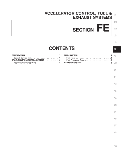
Image preview - the first page of the document
>> Download FE documenatation <<
Text preview - extract from the document
ACCELERATOR CONTROL, FUEL & GI
EXHAUST SYSTEMS
MA
SECTION FE EM
LC
EC
CONTENTS FE
PREPARATION................................................................2 FUEL SYSTEM ................................................................4
CL
Special Service Tool ....................................................2 Fuel Tank .....................................................................4
ACCELERATOR CONTROL SYSTEM ...........................3 Fuel Pump and Gauge ................................................7
Adjusting Accelerator Wire ..........................................3 EXHAUST SYSTEM ........................................................8 MT
AT
TF
PD
FA
RA
BR
ST
RS
BT
HA
EL
IDX
PREPARATION
Special Service Tool
The actual shapes of Kent-Moore tools may differ from those of special service tools illustrated here.
Tool number
(Kent-Moore No.) Description
Tool name
KV10114400 Loosening or tightening front and rear heated
(J-38365) oxygen sensors
Heated oxygen sensor
wrench
NT636 a = 22 mm (0.87 in)
Tool name
Description
(Kent-Moore No.)
Oxygen sensor Reconditioning the exhaust system threads
thread cleaner before installing a new oxygen sensor. Use
(J-43897-18) with anti-seize lubricant shown below.
(J-43897-12) A: J-43897-18 18 mm Diameter, for Zirconia
oxygen sensor
B: J-43897-12 12 mm Diameter, Titania oxy-
gen sensor.
AEM488
Anti-seize Lubricant Lubricating oxygen sensor thread, cleaning
PermatexTM 133AR tool when reconditioning exhaust system
or equivalent meeting threads.
MIL Specification
MIL-A-907
AEM489
FE-2
ACCELERATOR CONTROL SYSTEM
CAUTION: GI
q When removing accelerator wire, mark initial position of lock nut.
q Check that throttle valve opens fully when accelerator pedal is fully depressed. Check that throttle
valve returns to idle position when accelerator pedal is released. MA
q Check accelerator control parts for improper contact with any adjacent parts.
q When connecting accelerator wire, do not twist or scratch the inner wire.
q For adjustment of A/T throttle wire, refer to AT section (``Throttle Wire Adjustment'', ``ON-VEHICLE EM
SERVICE'').
LC
EC
FE
CL
MT
AT
TF
PD
FA
RA
BR
AFE107
ST
RS
BT
Adjusting Accelerator Wire
CAUTION:
q Make sure the ASCD wire is not pulling the throttle drum. HA
q For ASCD wire adjustment, refer to EL section [``AUTO-
MATIC SPEED CONTROL DEVICE (ASCD)''].
EL
1. Loosen lock nut, and tighten adjusting nut until throttle drum
starts to move.
2. Loosen adjusting nut 1.5 to 2 turns and tighten lock nut. IDX
SFE248AB
FE-3
FUEL SYSTEM
Fuel Tank
WARNING:
When replacing fuel line parts, be sure to observe the following:
q Put a ``CAUTION: FLAMMABLE'' sign in workshop.
q Do not smoke while servicing fuel system. Keep open flames and sparks away from work area.
q Furnish workshop with a CO2 fire extinguisher.
CAUTION:
q Before removing fuel line parts, carry out the following procedures:
a. Put drained fuel in an explosion-proof container and put the lid on securely.
b. Release fuel pressure from fuel line. Refer to EC section (``Fuel Pressure Release'', ``BASIC SER-
VICE PROCEDURE'').
c. Disconnect battery ground cable.
q When installing fuel check valve, install it in the correct direction. Refer to EC section (``EVAPO-
RATIVE EMISSION SYSTEM'').
q Always replace O-ring with a new one.
q Do not kink or twist tubes and hoses during installation.
q To avoid damaging hoses, do not tighten hose clamps excessively.
q After installing tubes, run engine and check for fuel leaks at connections.
q Use only a genuine fuel filler cap as a replacement. If an incorrect fuel filler cap is used, the MIL
may turn on.
AFE078
FE-4
FUEL SYSTEM
Fuel Tank (Cont'd)
REMOVAL GI
CAUTION:
q Do not disconnect any fuel line unless absolutely neces-
sary. MA
q Plug hose and pipe openings to prevent entry of dust and
dirt.
EM
LC
1. Release fuel pressure. Refer to EC section (``Fuel Pressure EC
Release'', ``BASIC SERVICE PROCEDURE'').
2. Disconnect battery ground cable.
3. Drain fuel from fuel tank. FE
4. Disconnect electrical connector.
5. Remove filler protector.
6. Disconnect filler tubes, EVAP hose, fuel supply tube and fuel CL
return tube.
MT
AFE076
7. Remove fuel tank protector. AT
TF
PD
FA
RA
BR
ST
RS
AFE081
8. Remove four fuel tank mounting bolts while supporting fuel
BT
tank.
HA
EL
IDX
AFE082
FE-5
FUEL SYSTEM
Fuel Tank (Cont'd)
9. Remove fuel tank.
AFE054
INSTALLATION
To install, reverse the removal procedure.
CAUTION:
q Do not kink or twist hoses and tubes during installation.
q To avoid damaging hoses, do not tighten hose clamps
excessively.
q Tighten bolts to specified torque.
q After installation, run engine and check for leaks at con-
nections.
FE-6
FUEL SYSTEM
Fuel Pump and Gauge GI
REMOVAL
1. Remove fuel tank. Refer to FE-5. MA
2. Disconnect fuel supply tube, fuel return tube and electrical
connector.
3. Remove the six screws. EM
LC
AFE076
4. Remove fuel pump and gauge. EC
FE
CL
MT
AT
TF
PD
FA
AFE077
INSTALLATION RA
To install, reverse the removal procedure.
CAUTION: BR
q Tighten bolts to specified torque.
: 2.0 - 2.5 N m (0.20 - 0.26 kg-m, 17.4 - 22.6 in-lb)
q Always replace O-ring with a new one. ST
q After installation, run engine and check for leaks at con-
nections.
RS
BT
HA
EL
IDX
FE-7
EXHAUST SYSTEM
CAUTION:
q Replace exhaust gaskets with new ones when reassem-
bling.
If gasket remains on flange surface, scrape off completely
as shown at left.
q With engine running, check all tube connections for
exhaust gas leaks, and entire system for unusual noises.
q Check to ensure that mounting brackets and mounting
insulators are installed properly and are free from undue
stress. Improper installation could result in excessive
SFE180A
noise or vibration.
q Discard any heated oxygen sensor dropped from a height
of more than 0.5 m (19.7 in) onto a hard surface such as
a concrete floor; use a new one.
q Before installing new oxygen sensor, clean exhaust sys-
tem threads using oxygen sensor thread cleaner Tool
J-43897-18 or J-43897-12 and approved anti-seize lubri-
cant.
FE-8
EXHAUST SYSTEM
GI
MA
EM
LC
EC
FE
CL
MT
AT
TF
PD
FA
RA
BR
ST
RS
BT
HA
EL
IDX
AFE080
FE-9
EXHAUST SYSTEM
AFE079
FE-10
◦ Jabse Service Manual Search 2026 ◦ Jabse Pravopis ◦ onTap.bg ◦ Other service manual resources online : Fixya ◦ eServiceinfo