Service Manuals, User Guides, Schematic Diagrams or docs for : . Car Manuals Nissan Frontier 1998-2002 Approved Nissan Frontier 2000 VG33E BR
<< Back | HomeMost service manuals and schematics are PDF files, so You will need Adobre Acrobat Reader to view : Acrobat Download Some of the files are DjVu format. Readers and resources available here : DjVu Resources
For the compressed files, most common are zip and rar. Please, extract files with Your favorite compression software ( WinZip, WinRAR ... ) before viewing. If a document has multiple parts, You should download all, before extracting.
Good luck. Repair on Your own risk. Make sure You know what You are doing.
Image preview - the first page of the document
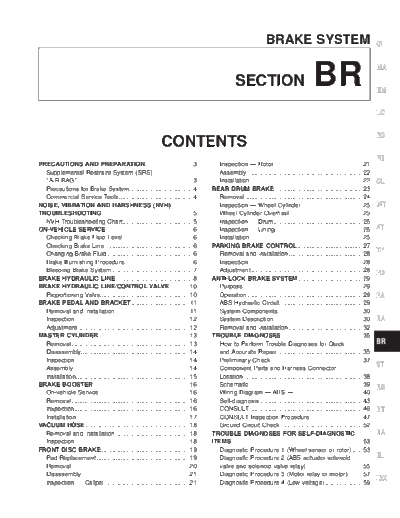
>> Download BR documenatation <<
Text preview - extract from the document
BRAKE SYSTEM GI
SECTION BR MA
EM
LC
EC
CONTENTS
FE
PRECAUTIONS AND PREPARATION............................3 Inspection -- Rotor....................................................21
Supplemental Restraint System (SRS) Assembly ...................................................................22
``AIR BAG'' ...................................................................3 Installation..................................................................22 CL
Precautions for Brake System.....................................4 REAR DRUM BRAKE ...................................................23
Commercial Service Tools ...........................................4 Removal.....................................................................24
NOISE, VIBRATION AND HARSHNESS (NVH) Inspection -- Wheel Cylinder ....................................25 MT
TROUBLESHOOTING .....................................................5 Wheel Cylinder Overhaul...........................................25
NVH Troubleshooting Chart.........................................5 Inspection -- Drum....................................................25
ON-VEHICLE SERVICE ..................................................6 Inspection -- Lining ...................................................25 AT
Checking Brake Fluid Level.........................................6 Installation..................................................................25
Checking Brake Line ...................................................6 PARKING BRAKE CONTROL ......................................27
Changing Brake Fluid ..................................................6 Removal and Installation ...........................................28
TF
Brake Burnishing Procedure........................................6 Inspection...................................................................28
Bleeding Brake System ...............................................7 Adjustment .................................................................28 PD
BRAKE HYDRAULIC LINE .........................................8 ANTI-LOCK BRAKE SYSTEM......................................29
BRAKE HYDRAULIC LINE/CONTROL VALVE............10 Purpose......................................................................29
Proportioning Valve....................................................10 Operation ...................................................................29 FA
BRAKE PEDAL AND BRACKET..................................11 ABS Hydraulic Circuit ................................................29
Removal and Installation ...........................................11 System Components .................................................30
Inspection...................................................................12 System Description....................................................30 RA
Adjustment .................................................................12 Removal and Installation ...........................................32
MASTER CYLINDER.....................................................13 TROUBLE DIAGNOSES ...............................................35
Removal.....................................................................13 How to Perform Trouble Diagnoses for Quick BR
Disassembly...............................................................14 and Accurate Repair ..................................................35
Inspection...................................................................14 Preliminary Check......................................................37
Assembly ...................................................................14 Component Parts and Harness Connector
ST
Installation..................................................................15 Location .....................................................................38
BRAKE BOOSTER........................................................16 Schematic ..................................................................39 RS
On-vehicle Service.....................................................16 Wiring Diagram -- ABS -- ........................................40
Removal.....................................................................16 Self-diagnosis ............................................................43
Inspection...................................................................16 CONSULT ..................................................................46 BT
Installation..................................................................17 CONSULT Inspection Procedure...............................47
VACUUM HOSE.............................................................18 Ground Circuit Check ................................................52
Removal and Installation ...........................................18 TROUBLE DIAGNOSES FOR SELF-DIAGNOSTIC HA
Inspection...................................................................18 ITEMS.............................................................................53
FRONT DISC BRAKE ...................................................19 Diagnostic Procedure 1 (Wheel sensor or rotor) ......53
Pad Replacement ......................................................19 Diagnostic Procedure 2 (ABS actuator solenoid EL
Removal.....................................................................20 valve and solenoid valve relay) .................................55
Disassembly...............................................................21 Diagnostic Procedure 3 (Motor relay or motor).........57
Inspection -- Caliper .................................................21 Diagnostic Procedure 4 (Low voltage) ......................59
IDX
CONTENTS (Cont'd.)
Diagnostic Procedure 5 (G sensor)...........................60 Diagnostic Procedure 12 (Warning lamp does
Diagnostic Procedure 6 (Control unit) .......................61 not come on when ignition switch is turned ON.) .....65
TROUBLE DIAGNOSES FOR SYMPTOMS.................62 Diagnostic Procedure 13 (Warning lamp stays on
Diagnostic Procedure 7 (ABS works frequently.) ......62 when ignition switch is turned ON.)...........................67
Diagnostic Procedure 8 (Unexpected pedal Electrical Components Inspection .............................69
action) ........................................................................63 SERVICE DATA AND SPECIFICATIONS (SDS) ..........70
Diagnostic Procedure 9 (Long stopping distance) ....63 General Specifications...............................................70
Diagnostic Procedure 10 (ABS does not work.) .......64 Inspection and Adjustment ........................................71
Diagnostic Procedure 11 (Pedal vibration and
noise) .........................................................................64
When you read wiring diagrams:
q Read GI section, ``HOW TO READ WIRING DIAGRAMS''.
q See EL section, ``POWER SUPPLY ROUTING'' for power distribution circuit.
When you perform trouble diagnoses, read GI section, ``HOW TO FOLLOW FLOW CHART
IN TROUBLE DIAGNOSES'' and ``HOW TO PERFORM EFFICIENT DIAGNOSIS FOR AN
ELECTRICAL INCIDENT''.
BR-2
PRECAUTIONS AND PREPARATION
Supplemental Restraint System (SRS) GI
``AIR BAG''
The Supplemental Restraint System ``AIR BAG'', used along with a seat belt, helps to reduce the risk or MA
severity of injury to the driver and front passenger in a frontal collision. The Supplemental Restraint System
consists of air bag modules (located in the center of the steering wheel and in the instrument panel on the
passenger side), a diagnosis sensor unit, a crash zone sensor, warning lamp, wiring harness and spiral cable. EM
The vehicle is equipped with a passenger air bag deactivation switch. Because no rear seat exists where a
rear-facing child restraint can be placed, the switch is designed to turn off the passenger air bag so that a
rear-facing child restraint can be used in the front passenger seat. The switch is located in the center of the LC
instrument panel, near the ashtray. When the switch is turned to the ON position, the passenger air bag is
enabled and could inflate in a frontal collision. When the switch is turned to the OFF position, the passenger
air bag is disabled and will not inflate in a frontal collision. A passenger air bag OFF indicator on the instru- EC
ment panel lights up when the passenger air bag is switch OFF. The driver air bag always remains enabled
and is not affected by the passenger air bag deactivation switch.
Information necessary to service the system safely is included in the RS section of this Service Manual. FE
WARNING:
q To avoid rendering the SRS inoperative, which could increase the risk of personal injury or death
in the event of a collision which would result in air bag inflation, all maintenance should be per- CL
formed by an authorized NISSAN dealer.
q Improper maintenance, including incorrect removal and installation of the SRS, can lead to per-
sonal injury caused by unintentional activation of the system. MT
q Do not use electrical test equipment on any circuit related to the SRS unless instructed to in this
Service Manual. SRS wiring harnesses are covered with yellow insulation either just before the
harness connectors or on the complete harness, for easy identification. AT
q The vehicle is equipped with a passenger air bag deactivation switch which can be operated by
the customer. When the passenger air bag is switched OFF, the passenger air bag is disabled and
will not inflate in a frontal collision. When the passenger air bag is switched ON, the passenger air TF
bag is enabled and could inflate in a frontal collision. After SRS maintenance or repair, make sure
the passenger air bag deactivation switch is in the same position (ON or OFF) as when the vehicle
arrived for service. PD
FA
RA
BR
ST
RS
BT
HA
EL
IDX
BR-3
PRECAUTIONS AND PREPARATION
Precautions for Brake System
q Use brake fluid DOT 3.
q Never reuse drained brake fluid.
q Be careful not to splash brake fluid on painted areas; it
may cause paint damage. If brake fluid is splashed on
painted areas, wash it away with water immediately.
q To clean master cylinder parts, disc brake caliper parts or
wheel cylinder parts, use clean brake fluid.
q Never use mineral oils such as gasoline or kerosene. They
will ruin rubber parts of the hydraulic system.
SBR686C q Use flare nut wrench when removing and installing brake
tubes.
q Always torque brake lines when installing.
q Burnish the brake contact surfaces after refinishing or
replacing drums or rotors, after replacing pads or linings,
or if a soft pedal occurs at very low mileage. Refer to
``Brake Burnishing Procedure'', ``ON-VEHICLE SERVICE'',
BR-6.
WARNING:
q Clean brakes with a vacuum dust collector to minimize the
hazard of airborne materials.
Commercial Service Tools
Tool name Description
1 Flare nut crowfoot Removing and installing each brake piping
2 Torque wrench
NT360 a: 10 mm (0.39 in)
Brake fluid pressure gauge Measuring brake fluid pressure
NT151
BR-4
Symptom
X: Applicable
Reference page
Possible cause and
SUSPECTED PARTS
BRAKE
Noise
Shake
Shimmy, Judder
X
Linings or pads - damaged BR-19, 25
X
Linings or pads - uneven wear BR-19, 25
X
Return spring damaged BR-23
X
Shims damaged BR-20
BR-5
X
X
Rotor or drum imbalance --
X
Rotor or drum damage --
X
Rotor or drum runout BR-21, 25
X
Rotor or drum deformation --
X
Rotor or drum deflection --
X
Rotor or drum rust --
X
NVH Troubleshooting Chart
Rotor thickness variation BR-22
X
Drum out of round BR-25
X
X
PROPELLER SHAFT NVH in PD section
X
DIFFERENTIAL NVH in PD section
X
X
X
AXLE AND SUSPENSION NVH in FA, RA section
X
X
X
TIRES NVH in FA section
NOISE, VIBRATION AND HARSHNESS (NVH) TROUBLESHOOTING
X
X
X
ROAD WHEEL NVH in FA section
X
X
DRIVE SHAFT NVH in RA section
Use the chart below to help you find the cause of the symptom. If necessary, repair or replace these parts.
X
X
X
STEERING NVH in ST section
GI
TF
AT
EL
FE
ST
FA
BT
CL
LC
RS
EC
RA
PD
HA
MT
BR
EM
MA
IDX
ON-VEHICLE SERVICE
Checking Brake Fluid Level
q Check fluid level in reservoir tank. It should be between Max
and Min lines on reservoir tank.
q If fluid level is extremely low, check brake system for leaks.
q If the brake warning lamp comes on, check brake fluid level
switch and parking brake switch.
SBR451D
Checking Brake Line
CAUTION:
If leakage occurs around joints, retighten or, if necessary,
replace damaged parts.
1. Check brake lines (tubes and hoses) for cracks, deterioration
or other damage. Replace any damaged parts.
2. Check for oil leakage by fully depressing brake pedal while
engine is running.
SBR389C
Changing Brake Fluid
CAUTION:
q Refill with new brake fluid DOT 3.
q Always keep fluid level higher than minimum line on res-
ervoir tank.
q Never reuse drained brake fluid.
q Be careful not to splash brake fluid on painted areas; it
may cause paint damage. If brake fluid is splashed on
painted areas, wash it away with water immediately.
1. Clean inside of reservoir tank, and refill with new brake fluid.
SBR992 2. Connect a vinyl tube to each air bleeder valve.
3. Drain brake fluid from each air bleeder valve by depressing
brake pedal.
4. Refill until brake fluid comes out of each air bleeder valve.
Use same procedure as in bleeding hydraulic system to refill
brake fluid. Refer to ``Bleeding Brake System'', BR-7.
Brake Burnishing Procedure
Burnish the brake contact surfaces according to the following pro-
cedure after refinishing or replacing drums or rotors, after replac-
ing pads or linings, or if a soft pedal occurs at very low mileage.
CAUTION:
Only perform this procedure under safe road and traffic con-
ditions. Use extreme caution.
1. Drive the vehicle on a straight smooth road at 50 km/h
(31 MPH).
2. Use medium brake pedal/foot effort to bring the vehicle to a
complete stop from 50 km/h (31 MPH). Adjust brake pedal/foot
pressure such that vehicle stopping time equals 3 to 5 sec-
onds.
3. To cool the brake system, drive the vehicle at 50 km/h
(31 MPH) for 1 minute without stopping.
4. Repeat steps 1 to 3, 10 times or more to complete the burnish-
ing procedure.
BR-6
ON-VEHICLE SERVICE
Bleeding Brake System GI
CAUTION:
q Carefully monitor brake fluid level at master cylinder dur- MA
ing bleeding operation.
q If master cylinder is suspected to have air inside, bleed air
from master cylinder first. Refer to ``Installation'', ``MAS- EM
TER CYLINDER'', BR-15.
q Fill reservoir with new brake fluid DOT 3. Make sure it is
full at all times while bleeding air out of system.
LC
q Place a container under master cylinder to avoid spillage
SBR995 of brake fluid.
q Turn ignition switch OFF and disconnect ABS actuator
and electric unit connector or battery cable.
EC
q Bleed air in the following order.
a. Left rear brake FE
b. Right rear brake
c. Left front brake
d. Right front brake CL
e. ABS actuator and electric unit
MT
1. Connect a transparent vinyl tube to air bleeder valve. AT
2. Fully depress brake pedal several times.
3. With brake pedal depressed, open air bleeder valve to release
air. TF
4. Close air bleeder valve.
5. Release brake pedal slowly.
6. Repeat steps 2 through 5 until clear brake fluid comes out of PD
air bleeder valve.
7. Tighten air bleeder to the specified torque.
: 7 - 9 N m (0.7 - 0.9 kg-m, 61 - 78 in-lb) FA
SBR419C
RA
BR
ST
RS
BT
HA
EL
IDX
BR-7
BRAKE HYDRAULIC LINE
ABR765
BR-8
BRAKE HYDRAULIC LINE
REMOVAL GI
CAUTION:
q Be careful not to splash brake fluid on painted areas; it
may cause paint damage. If brake fluid is splashed on MA
painted areas, wash it away with water immediately.
q All hoses must be free from excessive bending, twisting EM
and pulling.
1. Connect vinyl tube to air bleeder valve.
2. Drain brake fluid from each air bleeder valve by depressing LC
brake pedal.
SBR992 3. Remove flare nut connecting brake tube and hose, then with-
draw lock spring. EC
4. Cover openings to prevent entrance of dirt whenever discon-
necting brake line.
FE
INSPECTION
Check brake lines (tubes and hoses) for cracks, deterioration or
other damage. Replace any damaged parts. CL
MT
INSTALLATION AT
CAUTION:
q Refill with new brake fluid DOT 3. TF
q Never reuse drained brake fluid.
1. Tighten all flare nuts and connecting bolts.
Flare nut: PD
: 15 - 18 N m (1.5 - 1.8 kg-m, 11 - 13 ft-lb)
Connecting bolt:
: 17 - 19 N m (1.7 - 2.0 kg-m, 12 - 14 ft-lb) FA
2. Refill until new brake fluid comes out of each air bleeder valve.
SBR686C 3. Bleed air. Refer to ``Bleeding Brake System'', BR-7.
RA
BR
ST
RS
BT
HA
EL
IDX
BR-9
BRAKE HYDRAULIC LINE/CONTROL VALVE
Proportioning Valve
INSPECTION
CAUTION:
q Carefully monitor brake fluid level at master cylinder.
q Use new brake fluid ``DOT 3''.
q Be careful not to splash brake fluid on painted areas; it
may cause paint damage. If brake fluid is splashed on
painted areas, wash it away with water immediately.
q Depress pedal slowly when raising front brake pressure.
q Check rear brake pressure 2 seconds after front brake
ABR355 pressure reaches specified value.
q Disconnect harness connector from ABS actuator and
electric unit before checking.
1. Remove front LH tire.
2. Connect tool to air bleeders on front LH brake caliper and rear
LH or RH brake wheel cylinder.
3. Install front LH tire.
Before installing front LH tire, confirm the tool is not touching
the front LH wheel.
4. Bleed air from the tool.
5. Check fluid pressure by depressing brake pedal.
ABR184 Unit: kPa (kg/cm2, psi)
Applied pressure (Front brake) D1 5884 (60, 853)
Output pressure (Rear brake) D2 3285 - 3678
(33.5 - 37.5, 476 - 533)
If output pressure is out of specification, replace master cylinder
assembly.
6. Bleed air after disconnecting the tool. Refer to ``Bleeding Brake
System'', BR-7.
7. Install front LH tire.
SBR705AA
REMOVAL AND INSTALLATION
Always replace together with master cylinder as an assembly.
q Refer to ``MASTER CYLINDER'', BR-13.
BR-10
BRAKE PEDAL AND BRACKET
Removal and Installation GI
MA
EM
LC
EC
FE
CL
MT
AT
TF
PD
FA
ABR815
RA
BR
ST
RS
BT
HA
EL
IDX
BR-11
BRAKE PEDAL AND BRACKET
Inspection
Check brake pedal for following items:
q Brake pedal bend
q Clevis pin deformation
q Crack of any welded portion
q Crack or deformation of clevis pin stopper
SBR997
Adjustment
Check brake pedal free height from metal floor.
H: Free height
Refer to SDS, BR-71.
D: Depressed height
Refer to SDS, BR-71.
Under force of 490 N (50 kg, 110 lb)
with engine running
C: Clearance between pedal stopper and
threaded end of stop lamp switch
0.3 - 1.0 mm (0.012 - 0.039 in)
A: Pedal free play at pedal pad
1.0 - 3.0 mm (0.039 - 0.018 in)
SBR278AB
If necessary, adjust brake pedal free height.
1. Loosen lock nut and adjust pedal free height by turning brake
booster input rod. Then tighten lock nut.
q Make sure that the tip of input rod stays inside.
SBR930
2. Loosen lock nut and adjust clearance ``C'' with stop lamp
switch respectively, then tighten lock nut.
3. Check pedal free play.
q Make sure that stop lamp is off when pedal is released.
4. Check brake pedal's depressed height while engine is running.
If lower than specification, check for leaks, air in system, or
damage to components (master cylinder, wheel cylinder, etc.).
Make necessary repairs.
BR-12
MASTER CYLINDER
GI
MA
EM
LC
EC
FE
CL
MT
AT
TF
PD
FA
ABR766
RA
Removal
CAUTION:
q Be careful not to splash brake fluid on painted areas; it BR
may cause paint damage. If brake fluid is splashed on
painted areas, wash it away with water immediately.
q In the case of brake fluid leakage from the master cylinder, ST
disassemble the cylinder. Then check piston cups for
deformation or scratches and replace necessary parts.
1. Connect a vinyl tube to air bleeder valve. RS
2. Drain brake fluid from each air bleeder valve, depressing brake
pedal to empty fluid from master cylinder.
3. Remove brake pipe flare nuts. BT
4. Remove master cylinder mounting nuts.
HA
EL
IDX
BR-13
MASTER CYLINDER
Disassembly
1. Bend claws of stopper cap outward.
SBR938A
2. Remove piston assemblies.
q If it is difficult to remove secondary piston assembly,
gradually apply compressed air through fluid outlet.
3. Draw out reservoir tank.
SBR939A
Inspection
Check master cylinder inner wall for pin holes or scratches.
Replace if damaged.
Assembly
1. Insert secondary piston assembly. Then insert primary piston
assembly.
q Pay attention to direction of piston cups in figure at left.
Also, insert pistons squarely to avoid scratches on cylin-
der bore.
ABR767
2. Install stopper cap.
q Before installing stopper cap, ensure that claws are bent
inward.
3. Push reservoir tank seals into cylinder body.
4. Push reservoir tank into cylinder body.
SBR940A
BR-14
MASTER CYLINDER
Installation GI
CAUTION:
q Refill with new brake fluid DOT 3. MA
q Never reuse drained brake fluid.
1. Place master cylinder onto brake booster and secure mount-
ing nuts lightly. EM
2. Tighten mounting nuts.
: 12 - 15 N m (1.2 - 1.5 kg-m, 9 - 11 ft-lb)
3. Fill up reservoir tank with new brake fluid. LC
4. Plug all ports on master cylinder with fingers to prevent air
ABR190 suction while releasing brake pedal.
5. Have driver depress brake pedal slowly several times until no EC
air comes out of master cylinder.
6. Fit brake lines to master cylinder.
7. Tighten flare nuts. FE
: 15 - 18 N m (1.5 - 1.8 kg-m, 11 - 13 ft-lb)
8. Bleed air from brake system. Refer to ``Bleeding Brake
System'', BR-7. CL
MT
AT
TF
PD
FA
RA
BR
ST
RS
BT
HA
EL
IDX
BR-15
BRAKE BOOSTER
On-vehicle Service
OPERATING CHECK
q Depress brake pedal several times with engine off. After
exhausting vacuum, make sure there is no change in pedal
stroke.
q Depress brake pedal, then start engine. If pedal goes down
slightly, operation is normal.
SBR002A
AIRTIGHT CHECK
q Start engine, and stop it after one or two minutes. Depress
brake pedal several times slowly. Booster is airtight if pedal
stroke is less each time.
q Depress brake pedal while engine is running, and stop engine
with pedal depressed. The pedal stroke should not change
after holding pedal down for 30 seconds.
SBR365AA
Removal
CAUTION:
q Be careful not to splash brake fluid on painted areas; it
may cause paint damage. If brake fluid is splashed on
painted areas, wash it away with water immediately.
q Be careful not to deform or bend brake pipes during
removal of booster.
ABR373
Inspection
OUTPUT ROD LENGTH CHECK
1. Apply vacuum of -66.7 kPa (-500 mmHg, -19.69 inHg) to
brake booster with a handy vacuum pump.
2. Add preload of 19.6 N (2 kg, 4.4 lb) to output rod.
3. Check output rod length.
Specified length:
10.275 - 10.525 mm (0.4045 - 0.4144 in)
ABR749
BR-16
BRAKE BOOSTER
Installation GI
CAUTION:
q Be careful not to deform or bend brake pipes during instal- MA
lation of booster.
q Replace clevis pin if damaged.
q Refill with new brake fluid DOT 3. EM
q Never reuse drained brake fluid.
q Take care not to damage brake booster mounting bolt
thread when installing. Due to the narrow angle of
LC
installation, the threads can be damaged by the dash
SBR116BE panel.
A: 135 mm (5.31 in)
1. Before fitting booster, temporarily adjust clevis to dimension
EC
shown.
2. Fit booster, then secure mounting nuts (brake pedal bracket to
brake booster) lightly. FE
3. Connect brake pedal and booster input rod with clevis pin.
4. Secure mounting nuts.
: 13 - 16 N m (1.3 - 1.6 kg-m, 9 - 12 ft-lb) CL
5. Install master cylinder. Refer to ``Installation'', ``MASTER
CYLINDER'', BR-15.
6. Adjust brake pedal height and free play. Refer to BR-12.
MT
7. Secure lock nut for clevis.
: 16 - 22 N m (1.6 - 2.2 kg-m, 12 - 16 ft-lb)
AT
8. Bleed air. Refer to ``Bleeding Brake System'', BR-7.
TF
PD
FA
RA
BR
ST
RS
BT
HA
EL
IDX
BR-17
VACUUM HOSE
Removal and Installation
CAUTION:
When installing vacuum hoses, pay attention to the following
points.
q Do not apply any oil or lubricants to vacuum hose and
check valve.
q Insert vacuum tube into vacuum hose as shown.
SBR225B
q Install check valve, paying attention to its direction.
SBR498A
Inspection
HOSES AND CONNECTORS
Check vacuum lines and connections and check valve for
airtightness, improper attachment, chafing and deterioration.
CHECK VALVE
Check vacuum with a vacuum pump.
Connect to booster
Vacuum should exist.
side
Connect to engine
Vacuum should not exist.
side
SBR943A
BR-18
FRONT DISC BRAKE
Pad Replacement GI
WARNING:
Clean brake pads with a vacuum dust collector to minimize the MA
hazard of airborne materials.
CAUTION:
q When cylinder body is open, do not depress brake pedal EM
or caliper piston will pop out.
q Be careful not to damage piston boot or get oil on rotor.
Always replace shims when replacing pads. LC
q If shims are rusted or show peeling of the rubber coat,
replace them with new shims.
q It is not necessary to remove connecting bolt except for EC
disassembly or replacement of caliper assembly. In this
case, suspend cylinder body with wire so as not to stretch
brake hose. FE
q Burnish the brake contact surfaces after refinishing or
replacing drums or rotors, after replacing pads or linings,
or if a soft pedal occurs at very low mileage. Refer to CL
``Brake Burnishing Procedure'', ``ON-VEHICLE SERVICE'',
BR-6.
MT
1. Remove master cylinder reservoir cap. AT
2. Remove lower pin bolt.
TF
PD
FA
SBR081A
3. Open cylinder body upward. Then remove pad retainers, return RA
spring and inner and outer shims.
Standard pad thickness:
10 mm (0.39 in) BR
Pad wear limit:
2.0 mm (0.079 in)
q Carefully monitor brake fluid level because brake fluid will ST
return to reservoir when pushing back piston.
RS
BT
HA
EL
IDX
SBR010B
BR-19
FRONT DISC BRAKE
SBR983D
Removal
WARNING:
Clean brake pads with a vacuum dust collector to minimize the
hazard of airborne materials.
CAUTION:
Suspend caliper assembly with wire so as not to stretch brake
hose.
Remove torque member fixing bolts and connecting bolt.
q It is not necessary to remove connecting bolt except for
SBR083A
disassembly or replacement of caliper assembly. In this
case, suspend caliper assembly with wire so as not to
stretch brake hose.
BR-20
FRONT DISC BRAKE
Disassembly GI
WARNING:
Do not place your fingers in front of piston. MA
CAUTION:
q Do not scratch or score cylinder wall.
q CL28VD type front disc brake uses plastic pistons. Handle EM
them carefully.
1. Push out pistons and dust covers with compressed air.
Use a wooden block so that both pistons come out evenly. LC
2. Remove piston seals with a suitable tool.
SBR085A
Inspection -- Caliper EC
CYLINDER BODY
q Check inside surface of cylinders for scores, rust, wear, dam- FE
age or presence of foreign objects. If any of the above condi-
tions are observed, replace cylinder body.
q Minor damage from rust or foreign objects may be eliminated CL
by polishing the surface with a fine emery sandpaper. Replace
cylinder body if necessary.
CAUTION: MT
Use brake fluid to clean. Never use mineral oil.
PISTON AT
CAUTION:
Piston sliding surface is plated. Do not polish with emery sand- TF
paper even if rust or foreign objects are stuck to sliding surface.
Check pistons for uneven surface, chips or cracks. Replace if any
of these conditions are observed. PD
FA
SBR177C
SLIDE PIN, PIN BOLT AND PIN BOOT RA
Check for wear, cracks or other damage. Replace if any of these
conditions are observed. BR
ST
RS
BT
Inspection -- Rotor
RUNOUT
1. Check runout using a dial indicator. HA
q Make sure that wheel bearing axial end play is within
specification before measuring. Refer to FA section
EL
(``Front Wheel Bearing'', ``ON-VEHICLE SERVICE'').
Maximum runout:
0.07 mm (0.0028 in)
2. If the runout is out of specification, machine rotor with on-car
IDX
SBR089A
brake lathe (``MAD, DL-8700'', ``AMMCO 700 and 705'' or
equivalent).
BR-21
FRONT DISC BRAKE
Inspection -- Rotor (Cont'd)
THICKNESS
Thickness variation (At least 8 positions):
Maximum 0.02 mm (0.0008 in)
If thickness variation exceeds specification, machine rotor with on-
car brake lathe.
Rotor repair limit:
24.0 mm (0.945 in)
SBR090A
Assembly
1. Insert piston seal into groove on cylinder body.
2. With piston boot fitted to piston, insert piston boot into groove
on cylinder body and install piston.
3. Properly secure piston boot.
CAUTION:
q Secure dust seal properly.
q Lubricate with new brake fluid before installing plastic pis-
tons into cylinder body.
SBR178C
SBR179CA
Installation
CAUTION:
q Refill with new brake fluid DOT 3.
q Never reuse drained brake fluid.
1. Install caliper assembly.
2. Install brake hose to caliper securely.
3. Install all parts and secure all bolts.
4. Bleed air. Refer to ``Bleeding Brake System'', BR-7.
SBR084A
BR-22
REAR DRUM BRAKE
GI
MA
EM
LC
EC
FE
CL
MT
AT
TF
ABR768
PD
FA
RA
BR
ST
RS
BT
HA
EL
IDX
BR-23
REAR DRUM BRAKE
Removal
WARNING:
Clean brake lining with a vacuum dust collector to minimize
the hazard of airborne materials.
CAUTION:
Make sure parking brake lever is completely released.
1. Release parking brake lever fully, then remove drum.
q If drum is hard to remove, the following procedure should
be carried out.
a. Remove plug, then shorten adjuster to make clearance
between brake shoe and drum.
SBR280B
b. Install two bolts as shown. Tighten the two bolts gradually.
SBR093A
2. After removing retainer, remove spring by rotating shoes.
q Be careful not to damage wheel cylinder piston boots.
q Be careful not to damage parking brake cable when sepa-
rating it.
3. Remove adjuster.
4. Disconnect parking brake cable from toggle lever.
ABR369
5. Remove retainer clip with a suitable tool. Then separate toggle
lever and brake shoe.
ABR408
BR-24
REAR DRUM BRAKE
Inspection -- Wheel Cylinder GI
q Check wheel cylinder for leakage.
q Check for wear, damage and loose conditions. MA
Replace if any such condition exists.
EM
LC
ABR370
Wheel Cylinder Overhaul EC
q Check all internal parts for wear, rust and damage. Replace if
necessary. FE
q Pay attention not to scratch cylinder when installing pistons.
CL
MT
SBR215B
Inspection -- Drum AT
Maximum inner diameter (Repair limit):
LT30A 296.5 mm (11.67 in)
TF
q Contact surface should be finished with No. 120 to 150 emery
sandpaper.
q Using a brake lathe, machine brake drum if it shows score
marks, partial wear or stepped wear.
PD
q After brake drum has been completely reconditioned or
replaced, check drum and shoes for proper contact pattern.
FA
SBR095A
RA
Inspection -- Lining
Check lining thickness.
Standard lining thickness: BR
LT30A 6.1 mm (0.240 in)
Lining wear limit (A):
LT30A 1.5 mm (0.059 in) ST
RS
SBR021A
BT
Installation
q Always perform shoe clearance adjustment. Refer to
BR-28. HA
q Burnish the brake contact surfaces after refinishing or
replacing drums or rotors, after replacing pads or linings,
or if a soft pedal occurs at very low mileage. Refer to EL
``Brake Burnishing Procedure'', ``ON-VEHICLE SERVICE'',
BR-6.
1. Fit toggle lever to brake shoe with retainer clip. IDX
2. Apply brake grease to the contact areas shown at left.
ABR371
BR-25
REAR DRUM BRAKE
Installation (Cont'd)
3. Shorten adjuster by rotating it.
q Pay attention to direction of adjuster.
Wheel Screw
Left Left-hand thread
Right Right-hand thread
4. Connect parking brake cable to toggle lever.
5. Install all parts.
q Be careful not to damage wheel cylinder piston boots.
ABR396
6. Check all parts are installed properly.
q After installation is completed, adjust shoe-to-drum clear-
ance.
7. Install brake drum.
8. When installing new wheel cylinder or overhauling wheel
cylinder, bleed air. Refer to ``Bleeding Brake System'', BR-7.
9. Adjust parking brake. Refer to BR-28.
q Install all the parts by referring to the figure below.
ABR372
q After installing crank lever on back plate, make sure that there
is no play between crank lever and back plate. If play exists,
adjust bolt A and lock nut B .
SBR099A
ABR769
BR-26
PARKING BRAKE CONTROL
GI
MA
EM
LC
EC
FE
CL
MT
AT
TF
PD
FA
ABR770
RA
BR
ST
RS
BT
HA
EL
IDX
BR-27
PARKING BRAKE CONTROL
Removal and Installation
q Be careful not to damage cable.
q Make sure there is no free play after installation.
Inspection
1. Check control lever for wear or other damage. Replace if nec-
essary.
2. Check wires for discontinuity or deterioration. Replace ◦ Jabse Service Manual Search 2026 ◦ Jabse Pravopis ◦ onTap.bg ◦ Other service manual resources online : Fixya ◦ eServiceinfo