Service Manuals, User Guides, Schematic Diagrams or docs for : . Car Manuals Nissan Frontier 1998-2002 Approved Nissan Frontier 2000 VG33E CL
<< Back | HomeMost service manuals and schematics are PDF files, so You will need Adobre Acrobat Reader to view : Acrobat Download Some of the files are DjVu format. Readers and resources available here : DjVu Resources
For the compressed files, most common are zip and rar. Please, extract files with Your favorite compression software ( WinZip, WinRAR ... ) before viewing. If a document has multiple parts, You should download all, before extracting.
Good luck. Repair on Your own risk. Make sure You know what You are doing.
Image preview - the first page of the document
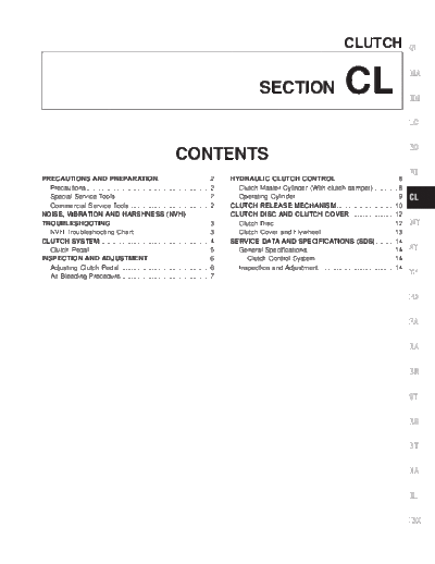
>> Download CL documenatation <<
Text preview - extract from the document
CLUTCH GI
SECTION CL MA
EM
LC
EC
CONTENTS
FE
PRECAUTIONS AND PREPARATION............................2 HYDRAULIC CLUTCH CONTROL .................................8
Precautions ..................................................................2 Clutch Master Cylinder (With clutch damper) .............8
Special Service Tools ..................................................2 Operating Cylinder.......................................................9 CL
Commercial Service Tools ...........................................2 CLUTCH RELEASE MECHANISM ...............................10
NOISE, VIBRATION AND HARSHNESS (NVH) CLUTCH DISC AND CLUTCH COVER ........................12
TROUBLESHOOTING .....................................................3 Clutch Disc.................................................................12 MT
NVH Troubleshooting Chart.........................................3 Clutch Cover and Flywheel .......................................13
CLUTCH SYSTEM...........................................................4 SERVICE DATA AND SPECIFICATIONS (SDS) ..........14
Clutch Pedal ................................................................5 General Specifications...............................................14 AT
INSPECTION AND ADJUSTMENT .................................6 Clutch Control System ..........................................14
Adjusting Clutch Pedal ................................................6 Inspection and Adjustment ........................................14
Air Bleeding Procedure................................................7
TF
PD
FA
RA
BR
ST
RS
BT
HA
EL
IDX
PRECAUTIONS AND PREPARATION
Precautions
q Recommended fluid is brake fluid DOT 3.
q Never reuse drained brake fluid.
q Be careful not to splash brake fluid on painted areas.
q When removing and installing clutch piping, use a suit-
able tool.
q Use new brake fluid to clean or wash all parts of master
cylinder, operating cylinder and clutch damper.
q Never use mineral oils such as gasoline or kerosene. They
will ruin the rubber parts of the hydraulic system.
SBR686C WARNING:
After cleaning the clutch disc, wipe it with a dust collector. Do
not use compressed air.
Special Service Tools
The actual shapes of Kent-Moore tools may differ from those of special service tools illustrated here.
Tool number
(Kent-Moore No.) Description
Tool name
ST20630000 Installing clutch cover and clutch disc
(J26366)
Clutch aligning bar
a: 15.9 mm (0.626 in) dia.
b: 22.8 mm (0.898 in) dia.
NT405 c: 55 mm (2.17 in)
ST20050240 Adjusting unevenness of clutch cover dia-
( -- ) phragm spring
Diaphragm spring
adjusting wrench
a: 150 mm (5.91 in)
NT404 b: 25 mm (0.98 in)
Commercial Service Tools
Tool name Description
1 Flare nut crowfoot Removing and installing clutch piping
2 Torque wrench
NT360 a: 10 mm (0.39 in)
Bearing puller Removing release bearing
NT077
Bearing drift Installing release bearing
a: 52 mm (2.05 in) dia.
NT474 b: 45 mm (1.77 in) dia.
CL-2
Reference page
(Possible cause)
SUSPECTED PARTS
Clutch slips
Symptom Clutch noisy
Clutch pedal spongy
Clutch grabs/chatters
Clutch does not disengage
1
1
CLUTCH PEDAL (Free play out of adjustment) CL-6
2
1
CLUTCH LINE (Air in line) CL-7
tion. If necessary, repair or replace these parts.
3
2
MASTER CYLINDER PISTON CUP (Damaged) CL-8
4
2
OPERATING CYLINDER PISTON CUP (Damaged) CL-9
1
ENGINE MOUNTING (Loose) Refer to EM section
CL-3
1
RELEASE BEARING (Worn, dirty or damaged) CL-10
5
CLUTCH DISC (Out of true) CL-12
2
5
CLUTCH DISC (Runout is excessive) CL-12
5
CLUTCH DISC (Lining broken) CL-12
5
CLUTCH DISC (Dirty or burned) CL-12
2
2
5
CLUTCH DISC (Oily) CL-12
NVH Troubleshooting Chart
2
2
CLUTCH DISC (Worn out) CL-12
2
CLUTCH DISC (Hardened) CL-12
5
CLUTCH DISC (Lack of spline grease) CL-12
3
6
DIAPHRAGM SPRING (Damaged) CL-13
2
6
DIAPHRAGM SPRING (Out of tip alignment) CL-13
NOISE, VIBRATION AND HARSHNESS (NVH) TROUBLESHOOTING
4
7
CLUTCH COVER (Distortion) CL-13
5
FLYWHEEL (Distortion) CL-13
Use the chart below to help you find the cause of the symptom. The numbers indicate the order of the inspec-
GI
TF
AT
EL
FE
ST
FA
BT
LC
RS
EC
RA
PD
CL
HA
BR
MT
EM
MA
IDX
CLUTCH SYSTEM
ACL096
CL-4
CLUTCH SYSTEM
Clutch Pedal GI
MA
EM
LC
EC
FE
CL
MT
AT
TF
ACL093
PD
FA
RA
BR
ST
RS
BT
HA
EL
IDX
CL-5
INSPECTION AND ADJUSTMENT
Adjusting Clutch Pedal
1. Adjust pedal height with pedal stopper bolt or ASCD clutch
switch.
Pedal height ``H'':
227 - 237 mm (8.94 - 9.33 in)
ACL075
2. Adjust pedal free play by turning master cylinder push rod.
Then tighten lock nut.
Pedal free play ``A'':
9 - 16 mm (0.35 - 0.63 in)
Pedal free play, measured at pedal pad includes the following:
q Free play due to clevis pin and clevis pin hole, push rod
and master cylinder.
3. Make sure that clevis pin can rotate smoothly.
If not, readjust pedal free play with master cylinder push rod.
ACL076
CL-6
INSPECTION AND ADJUSTMENT
Adjusting Clutch Pedal (Cont'd)
4. Adjust clearance ``C'' shown in the figure while fully depress- GI
ing clutch pedal.
Clearance ``C'':
0.1 - 1.0 mm (0.004 - 0.039 in) MA
EM
LC
EC
FE
CL
MT
ACL078
Air Bleeding Procedure AT
Bleed air according to the following procedure.
Bleed air from operating cylinder. TF
1. Fill the master cylinder reservoir tank with new brake fluid.
2. Connect a transparent vinyl hose to the air bleeder.
3. Slowly depress the clutch pedal to its full stroke length and PD
release it completely. Repeat this operation several times at 2
to 3 second intervals.
4. Open the air bleeder with the clutch pedal fully depressed. FA
5. Close the air bleeder.
SCL203 6. Release the clutch pedal and wait at least 5 seconds.
7. Repeat steps 3 through 6 above until air bubbles no longer RA
appear in the brake fluid.
BR
ST
RS
BT
HA
EL
IDX
CL-7
HYDRAULIC CLUTCH CONTROL
Clutch Master Cylinder (With clutch damper)
ACL097
DISASSEMBLY AND ASSEMBLY
q Use a screwdriver to remove stopper ring while pushing push
rod into cylinder.
q When installing stopper ring, tap in lightly while pushing push
rod into cylinder.
INSPECTION
Check the following items, and replace as necessary.
q Rubbing surface of cylinder and piston, for uneven wear, rust
and damage
q Piston with piston cup, for wear and damage
q Return spring, for wear and damage
q Dust cover, for cracks, deformation and damage
q Reservoir, for deformation and damage
CL-8
HYDRAULIC CLUTCH CONTROL
Operating Cylinder GI
MA
EM
LC
EC
FE
CL
MT
AT
TF
ACL090
PD
INSPECTION
Check the following items, and replace as necessary. FA
q Rubbing surface of cylinder and piston, for uneven wear, rust
and damage.
q Piston with piston cup, for wear and damage. RA
q Piston spring, for wear and damage.
q Dust cover, for cracks, deformation and damage.
BR
ST
RS
BT
HA
EL
IDX
CL-9
CLUTCH RELEASE MECHANISM
ACL095
REMOVAL AND INSTALLATION
q Remove release bearing.
CL145
q Install release bearing with suitable drift.
SCL705
q Install retainer spring and holder spring.
SCL217
CL-10
CLUTCH RELEASE MECHANISM
INSPECTION GI
Check the following items, and replace as necessary.
q Release bearing, to see that it rolls freely and is free from
noise, cracks, pitting and wear MA
q Release sleeve and withdrawal lever rubbing surface for wear,
rust and damage
EM
LC
LUBRICATION EC
q Apply recommended grease to contact surface and rubbing
surface.
FE
q Too much lubricant might damage clutch disc facing.
CL
MT
AT
SCL752 TF
PD
FA
WATERPROOF RA
q Apply recommended sealant to contact surface of transmission
case dust cover and withdrawal lever, then install dust cover BR
clip.
Recommended sealant: Nissan genuine part KP115-00100,
Three Bond TB1212, Loctite Part No. 51813 or equivalent. ST
RS
BT
HA
EL
IDX
ACL094
CL-11
CLUTCH DISC AND CLUTCH COVER
ACL092
Clutch Disc
INSPECTION
Check the following items, and replace as necessary.
q Clutch disc, for burns, discoloration and oil or grease leakage.
q Clutch disc, for wear of facing.
Wear limit of facing surface to rivet head:
0.3 mm (0.012 in)
ACL063
q Clutch disc, for backlash of spline and runout of facing.
Maximum backlash of spline (at outer edge of disc):
1.0 mm (0.039 in)
Runout limit:
1.0 mm (0.039 in)
Distance of runout check point (from hub center):
120 mm (4.72 in)
ACL064
CL-12
CLUTCH DISC AND CLUTCH COVER
Clutch Disc (Cont'd)
GI
INSTALLATION
q Apply recommended grease to contact surface of splines.
MA
q Too much lubricant may damage clutch disc facing.
EM
LC
Clutch Cover and Flywheel EC
INSPECTION AND ADJUSTMENT
q Check clutch cover installed on vehicle for uneven diaphragm FE
spring toe height.
Uneven limit:
0.5 mm (0.020 in) CL
q If out of limit, adjust the height using Tool.
MT
SCL466
FLYWHEEL INSPECTION AT
CAUTION:
Do not allow any magnetic materials to contact the ring gear TF
teeth.
q Inspect contact surface of flywheel for slight burns or discol-
oration. Clean flywheel using emery paper. PD
q Check flywheel runout.
Maximum allowable runout:
Refer to EM section (``Inspection'', ``CYLINDER FA
BLOCK'').
AEM100
INSTALLATION RA
q Insert Tool into clutch disc hub while installing clutch cover and
disc. BR
q Be careful not to allow grease to contaminate clutch facing.
q Tighten bolts in numerical order, in two steps.
First step: ST
: 10 - 20 N m (1.0 - 2.0 kg-m, 7 - 14 ft-lb)
Final step:
: 22 - 29 N m (2.2 - 3.0 kg-m, 16 - 22 ft-lb) RS
ACL079
BT
HA
EL
IDX
CL-13
SERVICE DATA AND SPECIFICATIONS (SDS)
General Specifications
CLUTCH CONTROL SYSTEM CLUTCH DISC
Unit: mm (in)
Type of clutch control Hydraulic
Model 250
Engine VG33E
CLUTCH MASTER CYLINDER (with clutch
damper) Facing size 250 x 160 x 3.5
(Outer dia. x inner dia. x thickness) (9.84 x 6.30 x 0.138)
Unit: mm (in)
8.1 - 8.5
Inner diameter 15.87 (5/8)
Thickness of disc assembly (0.3189 - 0.3346)
With load with 6473 N
CLUTCH OPERATING CYLINDER (660 kg - 1455 lb)
Unit: mm (in)
Inner diameter 19.05 (3/4) CLUTCH COVER
Model 250
Engine VG33E
Set-load N (kg, lb) 4658 (475, 1047)
Inspection and Adjustment
CLUTCH PEDAL CLUTCH DISC
Unit: mm (in) Unit: mm (in)
Pedal height ``H''* 227 - 237 (8.94 - 9.33) Model 250
Pedal free play ``A'' Wear limit of facing surface to rivet head 0.3 (0.012)
9 - 16 (0.35 - 0.63)
(at pedal pad)
Runout limit of facing 1.0 (0.039)
Clearance ``C'' between pedal
Distance of runout check point
stopper bracket and clutch pedal 120 (4.72)
0.1 - 1.0 (0.004 - 0.039) (from hub center)
position switch (with clutch pedal
fully depressed) Maximum backlash of spline
1.0 (0.039)
*: Measured from surface of dash lower panel to pedal pad. (at outer edge of disc)
CLUTCH COVER
Unit: mm (in)
Model 250
36.5 - 38.5
Diaphragm spring height
(1.437 - 1.516)
Uneven limit of diaphragm spring
0.5 (0.020)
toe height
CL-14
◦ Jabse Service Manual Search 2026 ◦ Jabse Pravopis ◦ onTap.bg ◦ Other service manual resources online : Fixya ◦ eServiceinfo