Service Manuals, User Guides, Schematic Diagrams or docs for : . Car Manuals Nissan Frontier 1998-2002 Approved Nissan Frontier 2000 VG33E LC

<< Back | Home

Most service manuals and schematics are PDF files, so You will need Adobre Acrobat Reader to view : Acrobat Download Some of the files are DjVu format. Readers and resources available here : DjVu Resources
For the compressed files, most common are zip and rar. Please, extract files with Your favorite compression software ( WinZip, WinRAR ... ) before viewing. If a document has multiple parts, You should download all, before extracting.
Good luck. Repair on Your own risk. Make sure You know what You are doing.


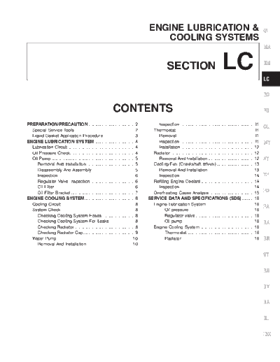
Image preview - the first page of the document
LC


>> Download LC documenatation <<

Text preview - extract from the document
                                                                                      ENGINE LUBRICATION &                                                                 GI
                                                                                         COOLING SYSTEMS
                                                                                                                                                                           MA


                                                                                                   SECTION                                  LC                             EM

                                                                                                                                                                           LC

                                                                                                                                                                           EC

                                                                CONTENTS                                                                                                   FE

PREPARATION/PRECAUTION .......................................2                           Inspection ..............................................................11
                                                                                                                                                                           CL
  Special Service Tools ..................................................2             Thermostat.................................................................11
  Liquid Gasket Application Procedure ..........................3                         Removal ................................................................11
ENGINE LUBRICATION SYSTEM ..................................4                             Inspection ..............................................................11      MT
  Lubrication Circuit ........................................................4           Installation .............................................................12
  Oil Pressure Check......................................................4             Radiator .....................................................................12
  Oil Pump ......................................................................5        Removal And Installation ......................................12                AT
     Removal And Installation ........................................5                 Cooling Fan (Crankshaft driven) ...............................13
     Disassembly And Assembly ....................................5                       Removal And Installation ......................................13
     Inspection ................................................................6         Inspection ..............................................................14      TF
     Regulator Valve Inspection .....................................6                  Refilling Engine Coolant ............................................14
     Oil Filter...................................................................6       Inspection ..............................................................14
     Oil Filter Bracket .....................................................7          Overheating Cause Analysis .....................................15                 PD
ENGINE COOLING SYSTEM..........................................8                      SERVICE DATA AND SPECIFICATIONS (SDS) ..........16
  Cooling Circuit .............................................................8        Engine Lubrication System........................................16
                                                                                                                                                                           FA
  System Check..............................................................8                  Oil pressure ......................................................16
     Checking Cooling System Hoses ...........................8                                Regulator valve.................................................16
     Checking Cooling System For Leaks .....................8                                  Oil pump ...........................................................16      RA
     Checking Radiator...................................................8              Engine Cooling System .............................................16
     Checking Radiator Cap...........................................9                         Thermostat........................................................16
  Water Pump ...............................................................10                 Radiator ............................................................16     BR
     Removal And Installation ......................................10

                                                                                                                                                                           ST

                                                                                                                                                                           RS

                                                                                                                                                                           BT

                                                                                                                                                                           HA

                                                                                                                                                                           EL

                                                                                                                                                                           IDX
                                             PREPARATION/PRECAUTION

                                                     Special Service Tools
The actual shapes of Kent-Moore tools may differ from those of special service tools illustrated here.
Tool number
(Kent-Moore No.)               Description
Tool name
ST25051001                                                                             Measuring oil pressure
(J25695-1)
Oil pressure gauge

                                                                                       Maximum measuring range:
                               NT558                                                   2,452 kPa (25 kg/cm2, 356 psi)
ST25052000                                                                             Adapting oil pressure gauge to cylinder block
(J25695-2)
Hose


                               NT559

KV10115801                                                                             Removing oil filter
(J38956)
Oil filter wrench


                               NT362

EG17650301                                                                             Adapting radiator cap tester to radiator filler
(J33984-A)                                                                             neck
Radiator cap tester adapter
                                                                                       a: 28 (1.10) dia.
                                                                                       b: 31.4 (1.236) dia.
                                                                                       c: 41.3 (1.626) dia.
                               NT564                                                   Unit: mm (in)
WS39930000                                                                             Pressing the tube of liquid gasket
(    --     )
Tube presser


                               NT052


                                                               LC-2
 PREPARATION/PRECAUTION

          Liquid Gasket Application Procedure                                 GI
          a.   Use a scraper to remove all traces of old liquid gasket
               from mating surface and grooves. Also, completely clean        MA
               any oil from these areas.
          b.   Apply a continuous bead of liquid gasket to mating sur-
               faces. (Use Genuine RTV silicone sealant part No. 999          EM
               MP-A7007 or equivalent.)
               q Be sure liquid gasket is 3.5 to 4.5 mm (0.138 to 0.177 in)
                  dia. (for oil pan).                                         LC
               q Be sure liquid gasket is 2.0 to 3.0 mm (0.079 to 0.118 in)
SEM371C           dia. (in areas except oil pan).
          c.   Apply liquid gasket around the inner side of bolt holes        EC
               (unless otherwise specified).
          d.   Assembly should be done within 5 minutes after coating.
          e.   Wait at least 30 minutes before refilling engine oil and       FE
               engine coolant.

                                                                              CL

                                                                              MT
 AEM080

                                                                              AT

                                                                              TF

                                                                              PD

                                                                              FA

                                                                              RA

                                                                              BR

                                                                              ST

                                                                              RS

                                                                              BT

                                                                              HA

                                                                              EL

                                                                              IDX


                   LC-3
ENGINE LUBRICATION SYSTEM

          Lubrication Circuit


                                                                           SLC082B


          Oil Pressure Check
          WARNING:
          q  Be careful not to burn yourself, as the engine and oil may
             be hot.
          q  Oil pressure check should be done in ``Neutral position''
             (M/T) or ``Parking position'' (A/T).
          1. Check oil level.
          2. Remove oil pressure switch.


 ALC120

          3.   Install pressure gauge.
          4.   Start engine and warm it up to normal operating temperature.
          5.   Check oil pressure with engine running under no-load.
                     Engine speed             Approximate discharge pressure
                         rpm                         kPa (kg/cm2, psi)
                       Idle speed                  More than 59 (0.6, 9)
                         2,000                 412 - 451 (4.2 - 4.6, 60 - 65)
          If difference is extreme, check oil passage and oil pump for oil
          leaks.
 SLC926   6. Install oil pressure switch with sealant.
                  : 12.25 - 17.15 N m (1.3 - 1.7 kg-m, 9-12 ft-lb)


                   LC-4
ENGINE LUBRICATION SYSTEM

     Oil Pump                                                            GI
     REMOVAL AND INSTALLATION
     1.  Drain engine oil.                                               MA
     2.  Drain engine coolant from drain plug on radiator.
     3.  Remove air duct (from mass air flow sensor to throttle body).
     4.  Remove cooling fan.                                             EM
     5.  Remove radiator hoses (upper and lower) and fan shroud.
         Refer to ``Radiator''.
     6. Remove drive belts. Refer to MA section (``Checking Drive        LC
         Belts'').
     7. Remove crankshaft pulley and front upper and lower belt cov-
         ers. Refer to EM section (``TIMING BELT'').                     EC
     8. Remove oil pan. Refer to EM section (``OIL PAN'').
     9. Remove oil strainer.
     10. Remove oil pump assembly.                                       FE

                                                                         CL

                                                                         MT


     DISASSEMBLY AND ASSEMBLY                                            AT

                                                                         TF

                                                                         PD

                                                                         FA

                                                                         RA

                                                                         BR

                                                                         ST

                                                                         RS

                                                              SLC117B
                                                                         BT
     q    Always replace with new oil seal and gasket.
     q    When installing oil pump, apply engine oil to inner and
          outer gears.                                            HA
     q    Be sure that O-ring is properly installed.

                                                                         EL

                                                                         IDX


             LC-5
ENGINE LUBRICATION SYSTEM
      Oil Pump (Cont'd)
          INSPECTION
          Using a feeler gauge, straightedge and micrometers, check the
          following clearances:
                                                                                Unit: mm (in)
              Body to outer gear radial clearance 1         0.114 - 0.200 (0.0045 - 0.0079)
              Inner gear to outer gear tip clearance 2            Below 0.18 (0.0071)
              Body to inner gear axial clearance 3           0.05 - 0.09 (0.0020 - 0.0035)
              Body to outer gear axial clearance 4          0.050 - 0.110 (0.0020 - 0.0043)

SLC072B       Inner gear to brazed portion of housing clear-
                                                             0.045 - 0.091 (0.0018 - 0.0036)
              ance 5
          q      If the tip clearance ( 2 ) exceeds the limit, replace gear set.
          q      If body to gear clearances ( 1 , 3 , 4 , 5 ) exceed the limit,
                 replace oil pump body assembly.


SLC073B


SLC934A

          REGULATOR VALVE INSPECTION
          1.   Visually inspect components for wear and damage.
          2.   Check oil pressure regulator valve sliding surface and valve
               spring.
          3. Coat regulator valve with engine oil. Check that it falls
               smoothly into the valve hole by its own weight.
          If damaged, replace regulator valve set or oil pump assembly.


SLC074B

          OIL FILTER
          The oil filter is a small, full-flow cartridge type and is provided with
          a relief valve.
          q    The new and previous oil filter designs differ from each
               other and are not interchangeable.
          q    Use Tool KV10115801 (J38956) for removing oil filter.


SLC035B


                      LC-6
ENGINE LUBRICATION SYSTEM
      Oil Pump (Cont'd)
          OIL FILTER BRACKET                                   GI
          1.   Remove oil filter.
          2.   Disconnect oil pressure switch and connector.
          3.   Remove oil filter bracket.                      MA

                                                               EM

                                                               LC
 ALC121

                                                               EC

                                                               FE

                                                               CL

                                                               MT

                                                               AT

                                                               TF

                                                               PD

                                                               FA

                                                               RA

                                                               BR

                                                               ST

                                                               RS

                                                               BT

                                                               HA

                                                               EL

                                                               IDX


                   LC-7
  ENGINE COOLING SYSTEM

          Cooling Circuit


                                                                     SLC080B


          System Check
          WARNING:
          Never remove the radiator cap when the engine is hot. Serious
          burns could occur from high pressure coolant escaping from
          the radiator.
          Wrap a thick cloth around the cap. Slowly turn it a quarter turn
          to allow built-up pressure to escape. Carefully remove the cap
          by turning it all the way.


          CHECKING COOLING SYSTEM HOSES
          Check hoses for improper attachment, leaks, cracks, damage,
          loose connections, chafing and deterioration.

          CHECKING COOLING SYSTEM FOR LEAKS
          To check for leakage, apply pressure to the cooling system with a
          tester.
                  Testing pressure: 157 kPa (1.6 kg/cm2, 23 psi)
          CAUTION:
          Higher pressure than specified may cause radiator damage.
SLC756A
          CHECKING RADIATOR
          Check radiator for mud or clogging. If necessary, clean radiator as
          follows.
          q    Be careful not to bend or damage the radiator fins.
          q    When radiator is cleaned without removal, remove all sur-
               rounding parts such as cooling fan, radiator shroud and horns.
          q    Tape the harness connectors to prevent water from entering.
          1. Apply water by hose to the back side of the radiator core ver-
               tically downward.
          2. Apply water again to all radiator core surfaces once per
               minute.


                  LC-8
  ENGINE COOLING SYSTEM
      System Check (Cont'd)
          3.   Stop washing when stains no longer flow out from the radia- GI
               tor.
          4.   Blow air into the back side of radiator core vertically downward.
          q    Use compressed air lower than 5 kg/cm2 and keep distance MA
               more than 30 cm (11.8 in).
          5.   Blow air again into all the radiator core surfaces once per
               minute until no water sprays out.                                 EM

                                                                               LC


          CHECKING RADIATOR CAP                                                EC
          To check radiator cap, apply pressure to cap with a tester.
                Radiator cap relief pressure:
                                                                               FE
                     Standard
                         78 - 98 kPa (0.8 - 1.0 kg/cm2, 11 - 14 psi)
                     Limit
                         59 - 98 kPa (0.6 - 1.0 kg/cm2, 9 - 14 psi)
                                                                               CL

                                                                               MT
SLC755A

                                                                               AT

                                                                               TF

                                                                               PD

                                                                               FA

                                                                               RA

                                                                               BR

                                                                               ST

                                                                               RS

                                                                               BT

                                                                               HA

                                                                               EL

                                                                               IDX


                   LC-9
  ENGINE COOLING SYSTEM

          Water Pump


                                                                     SLC076B

          CAUTION:
          q  When removing water pump assembly, be careful not to
             get coolant on timing belt.
          q  Water pump cannot be disassembled and should be
             replaced as a unit.
          q  After installing water pump, connect hose and clamp
             securely. Check for leaks using radiator cap tester.
          q  To avoid deforming timing cover, make sure there is
             adequate clearance between it and the hose clamp.


          REMOVAL AND INSTALLATION
          1.   Drain coolant from drain plugs on both sides of cylinder block
               and radiator. Refer to MA section (``Changing Engine Cool-
               ant'').


SMA207C


SMA208C


                  LC-10
  ENGINE COOLING SYSTEM
      Water Pump (Cont'd)
          2.   Remove radiator hoses (upper and lower) and fan shroud. GI
               Refer to ``Radiator''.
          3.   Remove drive belts. Refer to MA section (``Checking Drive
               Belts'').                                                 MA
          4.   Remove water pump pulley.
          5.   Remove crankshaft pulley and front (upper and lower) belt
               cover. Refer to EM section (``TIMING BELT'').             EM
          6.   Remove water pump.

                                                                             LC


          INSPECTION                                                         EC
          1.   Check for badly rusted or corroded body assembly and vanes.
          2.   Check for rough operation due to excessive end play.
                                                                             FE

                                                                             CL

                                                                             MT
 ALC107


          Thermostat                                                         AT

          REMOVAL
          1.   Drain engine coolant from drain plugs on radiator.            TF
          2.   Remove radiator hoses (upper and lower) and fan shroud.
          3.   Remove drive belts.
          4.   Remove pulley bracket.                                        PD
          5.   Remove water inlet and thermostat assembly.
                                                                             FA


          INSPECTION                                                         RA
          1.   Check valve seating condition at ordinary temperatures. It
               should seat tightly.                                       BR

                                                                             ST

                                                                             RS

                                                                             BT

                                                                             HA

                                                                             EL

                                                                             IDX
SLC081B


                  LC-11
  ENGINE COOLING SYSTEM
      Thermostat (Cont'd)
          2.      Check valve opening temperature and valve lift.
              Valve opening temperature            


◦ Jabse Service Manual Search 2026 ◦ Jabse PravopisonTap.bg ◦ Other service manual resources online : FixyaeServiceinfo