Service Manuals, User Guides, Schematic Diagrams or docs for : . Car Manuals Nissan Frontier 1998-2002 Approved Nissan Frontier 2000 VG33E PD
<< Back | HomeMost service manuals and schematics are PDF files, so You will need Adobre Acrobat Reader to view : Acrobat Download Some of the files are DjVu format. Readers and resources available here : DjVu Resources
For the compressed files, most common are zip and rar. Please, extract files with Your favorite compression software ( WinZip, WinRAR ... ) before viewing. If a document has multiple parts, You should download all, before extracting.
Good luck. Repair on Your own risk. Make sure You know what You are doing.
Image preview - the first page of the document
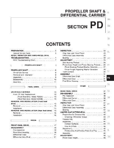
>> Download PD documenatation <<
Text preview - extract from the document
PROPELLER SHAFT & GI
DIFFERENTIAL CARRIER
MA
SECTION PD EM
LC
EC
CONTENTS FE
PREPARATION................................................................3 INSPECTION..................................................................23
CL
Special Service Tools ..................................................3 Ring Gear and Drive Pinion ......................................23
NOISE, VIBRATION AND HARSHNESS (NVH) Differential Case Assembly........................................23
TROUBLESHOOTING .....................................................7 Bearing.......................................................................23 MT
NVH Troubleshooting Chart.........................................7 ADJUSTMENT ...............................................................24
Side Bearing Preload.................................................24
PROPELLER SHAFT Pinion Gear Height and Pinion Bearing Preload.......25 AT
Pinion Bearing Preload Washer Selection............27
PROPELLER SHAFT ......................................................8 Pinion Height Adjusting Washer Selection............28
On-vehicle Service.......................................................9 Tooth Contact.............................................................30 TF
Removal and Installation .............................................9 ASSEMBLY....................................................................31
Inspection.....................................................................9 Differential Side Shaft................................................31
Differential Case ........................................................31 PD
Disassembly...............................................................10
Assembly ...................................................................11 Final Drive Housing ...................................................33
FA
FINAL DRIVE H233B
ON-VEHICLE SERVICE ................................................13 REAR FINAL DRIVE .....................................................37 RA
Front Oil Seal Replacement ......................................13 DISASSEMBLY..............................................................38
(Front final drive: Model R200A) ......................13 Pre-inspection ............................................................38
Differential Carrier......................................................38 BR
(Rear final drive: Model H233B).......................13
REMOVAL AND INSTALLATION (Front final Differential Case ........................................................40
drive)..............................................................................15 INSPECTION..................................................................42
Ring Gear and Drive Pinion ......................................42
ST
Removal.....................................................................15
Installation..................................................................15 Differential Case Assembly........................................42
REMOVAL AND INSTALLATION (Rear final drive) ....16 Bearing.......................................................................42 RS
Removal.....................................................................16 LIMITED SLIP DIFFERENTIAL.....................................43
Installation..................................................................16 Preparation for Disassembly .....................................43
Checking Differential Torque .................................43 BT
Disassembly...............................................................43
R200A
Inspection...................................................................44
Contact Surfaces...................................................44 HA
FRONT FINAL DRIVE ...................................................17 Disc And Plate.......................................................44
DISASSEMBLY..............................................................18 Adjustment .................................................................45
Pre-inspection ............................................................18 Friction Disc And Friction Plate End Play.............45 EL
Final Drive Housing ...................................................18 Assembly ...................................................................46
Differential Case ........................................................21 ADJUSTMENT ...............................................................49
Differential Side Shaft................................................21 Pinion Gear Height ....................................................49
IDX
CONTENTS (Cont'd.)
Pinion Height Adjusting Washer Selection............50 General Specifications ..........................................58
Tooth Contact.............................................................52 Inspection And Adjustment (R200A) .....................58
ASSEMBLY....................................................................53 Ring gear runout...............................................58
Differential Case ........................................................53 Side gear adjustment .......................................58
Differential Carrier......................................................54 Side bearing adjustment...................................58
SERVICE DATA AND SPECIFICATIONS (SDS) ..........57 Inspection And Adjustment (H233B) .....................59
Propeller Shaft ...........................................................57 Ring gear runout...............................................59
General Specifications ..........................................57 -- Additional service for LSD model --
Inspection And Adjustment....................................57 Differential torque adjustment...........................59
Service data......................................................57 Drive pinion height adjustment.........................60
Snap ring ..........................................................57 Drive pinion preload adjustment.......................60
Final Drive..................................................................58 Total preload adjustment ..................................60
PD-2
PREPARATION
Special Service Tools GI
The actual shapes of Kent-Moore tools may differ from those of special service tools illustrated here.
Tool number Unit application MA
(Kent-Moore No.) Description
Tool name R200A H233B
ST3127S000 Measuring pinion bearing preload and EM
(See J25765-A) total preload
Preload gauge
1 GG91030000 LC
(J25765)
Torque wrench
2 HT62940000
X X EC
( -- )
Socket adapter
3 HT62900000 FE
( -- )
Socket adapter NT124
CL
KV38100800 Mounting final drive
(J34310, J25604-01) (To use, make a new hole.)
Differential attachment
X -- MT
NT119 a: 152 mm (5.98 in)
AT
ST06340000 Mounting final drive
(J24310, J34310)
Differential attachment
-- X TF
NT140
PD
ST32580000 Adjusting side bearing preload and
(J34312) backlash (ring gear-drive pinion)
Differential side bearing FA
adjusting nut wrench -- X
NT141
RA
ST38060002 Removing and installing propeller shaft
(J34311) lock nut, and drive pinion lock nut BR
Drive pinion flange X --
wrench
NT113
ST
KV38104700 Removing and installing propeller shaft
(J34311) lock nut, and drive pinion lock nut RS
Drive pinion flange -- X
wrench
NT113 BT
ST3090S000 Removing and installing drive pinion
( -- ) rear inner cone
HA
Drive pinion rear inner
race puller set
1 ST30031000
(J22912-01)
X X EL
Puller
2 ST30901000 a: 79 mm (3.11 in) dia.
(J26010-01) b: 45 mm (1.77 in) dia.
IDX
Base NT527 c: 35 mm (1.38 in) dia.
PD-3
PREPARATION
Special Service Tools (Cont'd)
Tool number Unit application
(Kent-Moore No.) Description
Tool name R200A H233B
ST3306S001 Removing and installing differential side
Differential side bearing bearing inner cone
puller set
1 ST33051001
(J22888-20) X X
Body
2 ST33061000
(J8107-2) a: 28.5 mm (1.122 in) dia.
Adapter NT072 b: 38 mm (1.50 in) dia.
KV38100300 Installing side bearing inner cone
(J25523)
Differential side bearing
drift X --
a: 54 mm (2.13 in) dia.
b: 46 mm (1.81 in) dia.
NT085 c: 32 mm (1.26 in) dia.
ST33190000 Installing side bearing inner cone
(J25523)
Differential side bearing
drift -- X
a: 52 mm (2.05 in) dia.
b: 45.5 mm (1.791 in) dia.
NT085 c: 34 mm (1.34 in) dia.
ST33081000 Installing side bearing inner cone
( -- )
Side bearing puller
adapter -- X
a: 43 mm (1.69 in) dia.
NT431 b: 33.5 mm (1.319 in) dia.
KV38100600 Installing side bearing spacer
(J25267)
Side bearing spacer drift
X --
a: 8 mm (0.31 in)
NT528 b: R42.5 mm (1.673 in)
ST30611000 Installing pinion rear
(J25742-1) bearing outer race
Drift (Use with ST30621000 or ST30613000) X X
NT090
ST30621000 Installing pinion rear bearing outer race
(J25742-5) (Use with ST30611000)
Drift
X X
a: 79 mm (3.11 in) dia.
NT073 b: 59 mm (2.32 in) dia.
ST30613000 Installing pinion front bearing outer race
(J25742-3) (Use with ST30611000)
Drift
X X
a: 72 mm (2.83 in) dia.
NT073 b: 48 mm (1.89 in) dia.
PD-4
PREPARATION
Special Service Tools (Cont'd)
GI
Tool number Unit application
(Kent-Moore No.) Description
Tool name R200A H233B
MA
KV381025S0 Installing front oil seal
( -- )
Oil seal fitting tool EM
1 ST30720000
(J25405) -- X
Drift bar a: 77 mm (3.03 in) dia. LC
2 KV38102510 b: 55 mm (2.17 in) dia.
( -- ) c: 71 mm (2.80 in) dia.
Drift NT525 d: 65 mm (2.56 in) dia. EC
KV38100500 Installing front oil seal
(J25273)
Gear carrier front oil seal FE
X --
drift
a: 85 mm (3.35 in) dia.
NT115 b: 60 mm (2.36 in) dia. CL
KV38100200 Installing side oil seal
(J26233)
Gear carrier side oil seal MT
X --
drift
NT120 AT
(J34309) Adjusting bearing pre-load and gear
Differential shim height
selector TF
PD
X X
FA
NT134
RA
(J25269-4) Selecting pinion height adjusting washer
Side bearing discs
(2 Req'd)
X -- BR
NT136
ST
(J25269-18) Selecting pinion height adjusting washer
Side bearing discs
(2 Req'd) -- X RS
NT135
(J8129) Measuring carrier turning torque
BT
Spring gauge
X X HA
NT127
EL
IDX
PD-5
PREPARATION
Special Service Tools (Cont'd)
Tool number Unit application
(Kent-Moore No.) Description
Tool name R200A H233B
KV381052S0 Checking differential torque on limited
( -- ) slip differential
Rear axle shaft dummy
1 KV38105210
( -- ) -- X
Torque wrench side
2 KV38105220
( -- )
Vice side NT142
PD-6
Symptom
X : Applicable
Reference page
Possible cause and
SHAFT
SUSPECTED PARTS
PROPELLER
DIFFERENTIAL
Noise
Noise
Shake
Vibration
X
X
Uneven rotation torque --
X
X
X
Center bearing improper installlation PD-8, 11
X
X
Excessive center bearing axial end play --
X
X
Center bearing mounting (insulator) cracks, damage or deterioration --
X
X
X
Excessive joint angle --
PD-7
X
X
Rotation imbalance PD-9
X
X
Excessive runout PD-9
X
Rough gear tooth PD-23, 42
X
Improper gear contact PD-30, 52
X
Tooth surfaces worn PD-23, 42
X
Incorrect backlash PD-35, 56
X
Companion flange excessive runout --
NVH Troubleshooting Chart
X
Improper gear oil Refer to MA section
X
PROPELLER SHAFT Refer to PROPELLER SHAFT in this chart
X
DIFFERENTIAL Refer to DIFFERENTIAL in this chart
X
X
X
X
DRIVE SHAFT NVH in FA section
X
X
X
X
AXLE AND SUSPENSION NVH in FA, RA section
X
X
X
X
TIRES NVH in FA section
NOISE, VIBRATION AND HARSHNESS (NVH) TROUBLESHOOTING
X
X
X
ROAD WHEEL NVH in FA section
X
X
X
BRAKES NVH in BR section
Use the chart below to help you find the cause of the symptom. If necessary, repair or replace these parts.
X
X
X
X
STEERING NVH in ST section
GI
TF
AT
EL
FE
ST
FA
BT
CL
LC
RS
EC
RA
HA
BR
MT
PD
EM
MA
IDX
PROPELLER SHAFT PROPELLER SHAFT
Front propeller shaft (Model 2F1310)
APD025
Rear propeller shaft (Model 3S1310)
WPD017
PD-8
PROPELLER SHAFT PROPELLER SHAFT
On-vehicle Service GI
PROPELLER SHAFT VIBRATION
If vibration is present at high speed, inspect propeller shaft runout MA
first.
1. Raise rear end of vehicle until wheels are clear of the ground.
2. Measure propeller shaft runout at several points along propel- EM
ler shaft by rotating final drive companion flange using hands.
3. If runout exceeds specifications, disconnect propeller shaft at
final drive companion flange. Rotate companion flange 180 LC
SPD728
degrees, then reconnect propeller shaft.
Runout limit: 0.6 mm (0.024 in)
4. Check runout again. If runout still exceeds the limit, replace EC
propeller shaft assembly.
5. Perform road test.
FE
APPEARANCE CHECKING
q Inspect propeller shaft tube surface for dents or cracks and
replace as necessary. CL
q Check center bearing for noise or damage and replace as
necessary.
MT
SPD102
Removal and Installation AT
1. Place matching marks on flanges, then separate propeller
shaft from final drive. TF
PD
FA
SPD103
2. Remove propeller shaft. RA
q Insert plug into rear oil seal after removing rear propeller
shaft.
BR
ST
RS
SPD359
BT
Inspection
q Inspect propeller shaft runout. If runout exceeds the limit,
replace propeller shaft assembly. HA
Runout limit: 0.6 mm (0.024 in)
EL
IDX
SPD106
PD-9
PROPELLER SHAFT PROPELLER SHAFT
Inspection (Cont'd)
q Inspect journal axial play.
If play exceeds the limit, replace propeller shaft assembly.
Journal axial play:
0.02 mm (0.0008 in) or less
SPD874
Disassembly
CENTER BEARING
1. Place matching marks on flanges, then separate 2nd tube from
1st tube.
SPD109
2. Place matching marks on the flange and shaft.
SPD110
3. Remove locking nut using Tool.
Tool number:
ST38060002 (J34311)
4. Remove companion flange using puller.
SPD170A
5. Remove center bearing using Tool and press.
Tool number: ST30031000 (J22912-01)
SPD113
PD-10
PROPELLER SHAFT PROPELLER SHAFT
Disassembly (Cont'd)
JOURNAL GI
NOTE:
1. Place matching marks on propeller shaft and flange or yoke. MA
EM
LC
SPD128
2. Remove snap ring. EC
FE
CL
MT
APD011
3. Remove pushed out journal bearing by lightly tapping yoke AT
with a hammer, taking care not to damage journal and yoke
hole.
TF
PD
FA
SPD732
4. Remove bearing at opposite side in above operation. RA
Put marks on disassembled parts so that they can be
reinstalled in their original positions.
BR
ST
RS
SPD131
BT
Assembly
CENTER BEARING
HA
q When installing center bearing, position the ``F'' mark on cen-
ter bearing toward front of vehicle.
q Apply a coat of multi-purpose lithium grease containing EL
molybdenum disulfide to the end face of the center bearing
and both sides of the washer.
IDX
SPD114
PD-11
PROPELLER SHAFT PROPELLER SHAFT
Assembly (Cont'd)
q Stake the nut. Always use new one.
q Align match marks when assembling tubes.
SPD117
JOURNAL
1. Assemble journal bearing. Apply recommended multi-purpose
grease on bearing inner surface.
When assembling, be careful that needle bearing does not fall
down.
SPD133
2. Select snap ring that will provide specified play in axial direction
of journal, and install them.
Refer to SDS, PD-57.
Select snap rings with a difference in thickness at both sides
within 0.06 mm (0.0024 in).
APD012
3. Adjust thrust clearance between bearing and snap ring to zero
by tapping yoke.
SPD732
4. Check to see that journal moves smoothly and check for axial
play.
Axial play: 0.02 mm (0.0008 in) or less
SPD874
PD-12
ON-VEHICLE SERVICE FINAL DRIVE
Front Oil Seal Replacement GI
(Front final drive: Model R200A)
1. Remove front propeller shaft.
2. Loosen drive pinion nut. MA
Tool number: ST38060002 (J34311)
EM
LC
SPD733
3. Remove companion flange. EC
FE
CL
MT
SPD734
4. Remove front oil seal. AT
TF
PD
FA
SPD735
5. Apply multi-purpose grease to cavity at sealing lips of oil seal. RA
Press front oil seal into carrier.
Tool number:
KV38100500 (J25273) BR
6. Install companion flange and drive pinion nut.
7. Install propeller shaft.
ST
RS
SPD736
BT
(Rear final drive: Model H233B)
1. Remove rear propeller shaft.
2. Loosen drive pinion nut. HA
Tool number: KV38104700 (J34311)
EL
IDX
PD237
PD-13
ON-VEHICLE SERVICE FINAL DRIVE
Front Oil Seal Replacement (Cont'd)
3. Remove companion flange.
SPD737
4. Remove front oil seal.
SPD738
5. Apply multi-purpose grease to cavity at sealing lips of oil seal.
Press front oil seal into carrier.
Tool number:
ST30720000 (J25405)
KV38102510 ( -- )
6. Install companion flange and drive pinion nut.
7. Install rear propeller shaft.
SPD739
PD-14
REMOVAL AND INSTALLATION (Front final drive) FINAL DRIVE
Removal GI
1. Remove front propeller shaft.
2. Separate drive shaft from front final drive. Refer to FA section MA
[``Drive Shaft'', ``FRONT AXLE (4WD)''].
3. Remove engine mounting bolts and raise up engine.
4. Remove front final drive together with differential mounting EM
member.
LC
SPD741
Installation EC
1. Install front final drive assembly together with differential
mounting member. FE
CL
MT
SPD742
2. Tighten front final drive securing bolts and nuts by following the AT
procedure to prevent drive train vibration.
a. Temporarily tighten nut A .
b. Temporarily tighten nut B . TF
c. Tighten bolt C to the torque of 68 to 87 N m (6.9 to 8.9 kg-m,
50 to 64 ft-lb).
d. Tighten bolt D to the torque of 68 to 87 N m (6.9 to 8.9 kg-m, PD
50 to 64 ft-lb).
e. Tighten nut A to the torque of 68 to 87 N m (6.9 to 8.9 kg-m,
50 to 64 ft-lb). FA
f. Tighten nut B to the torque of 68 to 87 N m (6.9 to 8.9 kg-m,
50 to 64 ft-lb).
g. Tighten nut E to the torque of 68 to 87 N m (6.9 to 8.9 kg-m, RA
50 to 64 ft-lb).
3. Install drive shaft. Refer to FA section [``Drive Shaft'', ``FRONT
AXLE (4WD)'']. BR
4. Install front propeller shaft.
ST
RS
SPD743
BT
HA
EL
IDX
PD-15
REMOVAL AND INSTALLATION (Rear final drive) FINAL DRIVE
Removal
q Remove propeller shaft.
Plug front end of transfer.
q Remove axle shaft.
Refer to RA section (``REAR AXLE'').
CAUTION:
q Be careful not to damage spline, sleeve yoke and front oil
seal when removing propeller shaft.
q Before removing the final drive assembly or rear axle
assembly, disconnect the ABS sensor harness connector
from the assembly and move it away from the final drive/
rear axle assembly area. Failure to do so may result in the
sensor wires being damaged and the sensor becoming
inoperative.
Installation
q Fill final drive with recommended gear oil.
SPD123
PD-16
FRONT FINAL DRIVE R200A
GI
MA
EM
LC
EC
FE
CL
MT
AT
TF
PD
FA
RA
BR
ST
RS
BT
HA
EL
IDX
APD020
PD-17
DISASSEMBLY R200A
Pre-inspection
Before disassembling final drive, perform the following inspection.
q Total preload
1) Turn drive pinion in both directions several times to set bear-
ing rollers.
2) Check total preload with Tool.
Tool number: ST3127S000 (J25765-A)
Total preload:
1.4 - 1.7 N m (14 - 17 kg-cm, 12 - 15 in-lb)
SPD664
q Ring gear to drive pinion backlash
Check backlash of ring gear with a dial indicator at several
points.
Ring gear-to-drive pinion backlash:
0.10 - 0.15 mm (0.0039 - 0.0059 in)
SPD513
q Ring gear runout
Check runout of ring gear with a dial indicator.
Runout limit:
0.05 mm (0.0020 in)
q Tooth contact
Check tooth contact. Refer to ADJUSTMENT (PD-30).
SPD524
q Side gear to pinion mate gear backlash
Using a feeler gauge, measure clearance between side gear
thrust washer and differential case.
Clearance between side gear thrust washer
and differential case:
Less than 0.15 mm (0.0059 in)
SPD665
Final Drive Housing
1. Using three spacers [20 mm (0.79 in)], mount final drive
assembly on Tool.
Tool number:
KV38100800 (J34310, J25604-01)
SPD666
PD-18
DISASSEMBLY R200A
Final Drive Housing (Cont'd)
2. Remove differential side shaft assembly. GI
MA
EM
LC
SPD644
3. Remove differential side flange. EC
FE
CL
MT
SPD667
4. Put match marks on one side of side bearing cap with paint or AT
punch to ensure that it is replaced in proper position during
reassembly.
Bearing caps are line-bored during manufacture and should TF
be put back in their original places.
PD
FA
SPD526
5. Remove side bearing caps. RA
BR
ST
RS
PD343
6. Remove differential case assembly with a pry bar.
BT
HA
EL
IDX
SPD668
PD-19
DISASSEMBLY R200A
Final Drive Housing (Cont'd)
Be careful to keep the side bearing outer races together with
their respective inner cones -- don't mix them up.
CAUTION:
Side bearing spacer is placed on either the left or right
depending upon final drive gear ratio. It should be labeled so
that it may be replaced correctly.
SPD527
7. Loosen drive pinion nut.
Tool number: ST38060002 (J34311)
8. Remove companion flange with puller.
SPD171A
9. Take out drive pinion together with rear bearing inner cone,
drive pinion bearing spacer and pinion bearing adjusting
washer.
10. Remove front oil seal and pinion front bearing inner cone.
SPD670
11. Remove pinion bearing outer races with a brass drift.
PD349
12. Remove pinion rear bearing inner cone and drive pinion height
adjusting washer.
Tool number: ST30031000 (J22912-01)
SPD209
PD-20
DISASSEMBLY R200A
Differential Case GI
1. Remove side bearing inner cones.
To prevent damage to bearing, engage puller jaws in grooves. MA
Tool number:
A ST33051001 (J22888-20)
B ST33061000 (J8107-2) EM
LC
SPD207A
Be careful not to confuse the right and left hand parts. EC
Keep bearing and bearing race for each side together.
FE
CL
MT
SPD022
2. Loosen ring gear bolts in a criss-cross pattern. AT
3. Tap ring gear off the differential case with a soft hammer.
Tap evenly all around to keep ring gear from binding.
TF
PD
FA
SPD024
4. Punch off pinion mate shaft lock pin from ring gear side. RA
BR
ST
RS
SPD025
BT
Differential Side Shaft
1. Cut collar with cold chisel. Be careful not to damage differen-
tial side shaft. HA
EL
IDX
SPD236A
PD-21
DISASSEMBLY R200A
Differential Side Shaft (Cont'd)
2. Reinstall differential side shaft into extension tube and secure
with bolts. Remove rear axle bearing by drawing out differen-
tial side shaft from rear axle bearing with puller.
SPD672
3. Remove grease seal and oil seal.
SPD647
SPD781
PD-22
INSPECTION R200A
Ring Gear and Drive Pinion GI
Check gear teeth for scoring, cracking or chipping.
If any damaged part is evident, replace ring gear and drive pinion MA
as a set (hypoid gear set).
EM
LC
Differential Case Assembly EC
Check mating surfaces of differential case, side gears, pinion mate
gears, pinion mate shaft and thrust washers. FE
CL
MT
SPD097AA
Bearing AT
1. Thoroughly clean bearing.
2. Check bearing for wear, scratches, pitting or flaking. TF
Check tapered roller bearing for smooth rotation. If damaged,
replace outer race and inner cone as a set.
PD
FA
SPD715
RA
BR
ST
RS
BT
HA
EL
IDX
PD-23
ADJUSTMENT R200A
For quiet and reliable final drive operation, the following five adjust-
ments must be made correctly:
1. Side bearing preload
2. Pinion gear height
3. Pinion bearing preload
4. Ring gear-to-pinion backlash. Refer to ASSEMBLY (PD-35).
5. Ring and pinion gear tooth contact pattern
Side Bearing Preload
A selection of carrier side bearing adjusting washer is
required for successful completion of this procedure.
1. Make sure all parts are clean and that the bearings are well
TM
lubricated with light oil or ``DEXRON '' type automatic transmission
fluid.
2. Place the differential carrier, with side bearings and bearing
races installed, into the final drive housing.
SPD527
3. Put the side bearing spacer in place.
CAUTION:
Side bearing spacer is placed on either the right or left
depending upon final drive gear ratio. Be sure to replace it on
the correct side.
SPD894
4. Using Tool, install original carrier side bearing preload shims
on the carrier end, opposite the ring gear.
Tool number: KV38100600 (J25267)
SPD986
PD-24
ADJUSTMENT R200A
Side Bearing Preload (Cont'd)
5. Install the side bearing caps in their correct locations and GI
torque the bearing cap retaining bolts.
Specification:
88 - 98 N m (9 - 10 kg-m, 65 - 72 ft-lb) MA
6. Turn the carrier several times to seat the bearings.
EM
LC
SPD526
7. Measure the turning torque of the carrier at the ring gear retain- EC
ing bolts with a spring gauge, J8129.
Specification:
34.3 - 39.2 N (3.5 - 4.0 kg, 7.7 - 8.8 lb) FE
of pulling force at the ring gear bolt.
CL
MT
SPD194A
8. If the carrier turning torque is not within the specification range, AT
increase or decrease the total thickness of the side bearing
adjusting washers until the turning torque is correct. If the
turning torque is less than the specified range, install washers TF
of greater thickness; if the turning torque is greater than the
specification, install thinner washers. See the SDS section for
washer dimensions and part numbers. PD
9. Record the total amount of washer thickness required for the
correct carrier side bearing preload.
FA
SPD772
10. Remove the carrier from the final drive housing, saving the RA
selected preload washers for later use during the assembly of
the final drive unit.
BR
ST
RS
SPD668
BT
Pinion Gear Height and Pinion Bearing Preload
1. Make sure all parts are clean and that the bearings are well
lubricated. HA
2. Assemble the pinion gear bearings into the pinion pre-load
shim selector Tool, J34309.
EL
IDX
SPD769
◦ Jabse Service Manual Search 2026 ◦ Jabse Pravopis ◦ onTap.bg ◦ Other service manual resources online : Fixya ◦ eServiceinfo