Service Manuals, User Guides, Schematic Diagrams or docs for : . Car Manuals Nissan Pathfinder 1999-2003 Approved Nissan Pathfinder 2001 ha
<< Back | HomeMost service manuals and schematics are PDF files, so You will need Adobre Acrobat Reader to view : Acrobat Download Some of the files are DjVu format. Readers and resources available here : DjVu Resources
For the compressed files, most common are zip and rar. Please, extract files with Your favorite compression software ( WinZip, WinRAR ... ) before viewing. If a document has multiple parts, You should download all, before extracting.
Good luck. Repair on Your own risk. Make sure You know what You are doing.
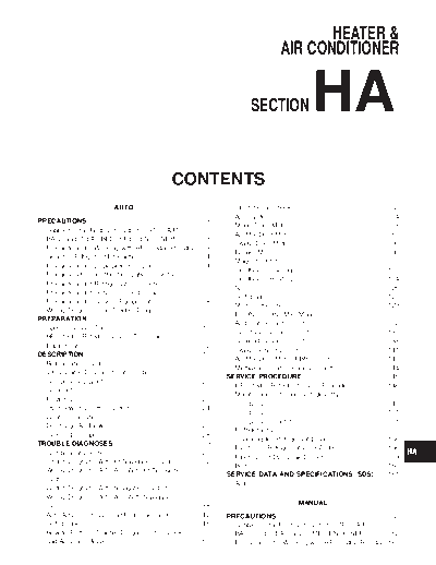
Image preview - the first page of the document

>> Download ha documenatation <<
Text preview - extract from the document
HEATER & GI
AIR CONDITIONER
MA
SECTION HA EM
LC
EC
FE
CONTENTS CL
AUTO Operational Check .....................................................68
MT
A/C System................................................................74
PRECAUTIONS ...............................................................3
Mode Door Motor.......................................................78
Supplemental Restraint System (SRS) AIR
BAG and SEAT BELT PRE-TENSIONER...............3
Air Mix Door Motor ....................................................85 AT
Intake Door Motor......................................................90
Precautions for Working with HFC-134a (R-134a) .....3
Blower Motor..............................................................98
General Refrigerant Precautions .................................4 TF
Magnet Clutch..........................................................107
Precautions for Leak Detection Dye............................4
Insufficient Cooling ..................................................115
Precaution for Identification Label on Vehicle .............5
Insufficient Heating ..................................................124
Precautions for Refrigerant Connection ......................5
Noise........................................................................126
PD
Precautions for Servicing Compressor........................7
Self-diagnosis ..........................................................127
Precautions for Service Equipment .............................8
Memory Function .....................................................129 AX
Wiring Diagrams and Trouble Diagnoses..................10
ECON (ECONOMY) Mode ......................................131
PREPARATION .............................................................11
Ambient Sensor Circuit............................................132
Special Service Tools ................................................11
In-vehicle Sensor Circuit..........................................135 SU
HFC-134a (R-134a) Service Tools and
Sunload Sensor Circuit............................................138
Equipment..................................................................12
Intake Sensor Circuit ...............................................141
DESCRIPTION ...............................................................15
Air Mix Door Motor PBR Circuit ..............................143 BR
Refrigeration System .................................................15
Multiplex Communication Circuit .............................144
V-6 Variable Displacement Compressor....................16
SERVICE PROCEDURE..............................................146 ST
Component Layout ....................................................20
HFC-134a (R-134a) Service Procedure ..................146
Introduction ................................................................21
Maintenance of Lubricant Quantity in
Features.....................................................................21
Overview of Control System......................................24
Compressor .............................................................148 RS
Compressor .............................................................151
Control Operation ......................................................25
Compressor Clutch ..................................................151
Discharge Air Flow.....................................................27 BT
Refrigerant Lines .....................................................155
System Description....................................................28
Checking for Refrigerant Leaks...............................156
TROUBLE DIAGNOSES................................................29
Electronic Refrigerant Leak Detector ......................156
Component Location..................................................29
Fluorescent Dye Leak Detector...............................159
Circuit Diagram (Without Navigation System)...........32
Belt...........................................................................160
Wiring Diagram - A/C, A - (Without Navigation
System)......................................................................33
SERVICE DATA AND SPECIFICATIONS (SDS) .......161 SC
Auto..........................................................................161
Circuit Diagram (With Navigation System)................37
Wiring Diagram - A/C, A - (With Navigation EL
MANUAL
System)......................................................................38
Auto Amp. Terminals and Reference Value...............42 PRECAUTIONS ...........................................................162
Self-diagnosis ............................................................46 Supplemental Restraint System (SRS) AIR IDX
How to Perform Trouble Diagnoses for Quick BAG and SEAT BELT PRE-TENSIONER...........162
and Accurate Repair ..................................................67 Precautions for Working with HFC-134a (R-134a) .162
CONTENTS (Cont'd)
General Refrigerant Precautions .............................163 How to Perform Trouble Diagnoses for Quick
Precautions for Leak Detection Dye........................163 and Accurate Repair ................................................190
Precaution for Identification Label on Vehicle .........164 Operational Check ...................................................191
Precautions for Refrigerant Connection ..................164 Intake Door ..............................................................193
Precautions for Servicing Compressor....................166 Blower Motor............................................................200
Precautions for Service Equipment .........................167 Insufficient Cooling ..................................................207
Wiring Diagrams and Trouble Diagnoses................169 Insufficient Heating ..................................................215
PREPARATION ...........................................................170 Air Outlet..................................................................217
Special Service Tools ..............................................170 Magnet Clutch..........................................................219
HFC-134a (R-134a) Service Tools and Noise........................................................................226
Equipment................................................................171 SERVICE PROCEDURE..............................................227
DESCRIPTION .............................................................174 HFC-134a (R-134a) Service Procedure ..................227
Refrigeration System ...............................................174 Maintenance of Lubricant Quantity in
V-6 Variable Displacement Compressor..................175 Compressor .............................................................229
Component Layout ..................................................179 Compressor .............................................................232
Control Operation ....................................................180 Compressor Clutch ..................................................232
Discharge Air Flow...................................................181 Refrigerant Lines .....................................................236
System Description..................................................182 Checking for Refrigerant Leaks...............................237
TROUBLE DIAGNOSES..............................................183 Electronic Refrigerant Leak Detector ......................237
Component Location................................................183 Fluorescent Dye Leak Detector...............................240
Wiring Diagram - HEATER -....................................185 Belt...........................................................................241
Circuit Diagram - Air Conditioner.............................186 SERVICE DATA AND SPECIFICATIONS (SDS) .......242
Wiring Diagram - A/C, M - .......................................187 Manual .....................................................................242
HA-2
PRECAUTIONS AUTO
Supplemental Restraint System (SRS) "AIR BAG" and "SEAT BELT PRE-TENSIONER"
Supplemental Restraint System (SRS) "AIR GI
BAG" and "SEAT BELT PRE-TENSIONER" NAHA0153
The Supplemental Restraint System such as "AIR BAG" and "SEAT BELT PRE-TENSIONER" used along with
a seat belt, helps to reduce the risk or severity of injury to the driver and front passenger for certain types of
MA
collision. The SRS system composition which is available to NISSAN MODEL R50 is as follows:
◦ Jabse Service Manual Search 2024 ◦ Jabse Pravopis ◦ onTap.bg ◦ Other service manual resources online : Fixya ◦ eServiceinfo