Service Manuals, User Guides, Schematic Diagrams or docs for : . Car Manuals Nissan Pickup 1998-2006 Approved s3 el
<< Back | HomeMost service manuals and schematics are PDF files, so You will need Adobre Acrobat Reader to view : Acrobat Download Some of the files are DjVu format. Readers and resources available here : DjVu Resources
For the compressed files, most common are zip and rar. Please, extract files with Your favorite compression software ( WinZip, WinRAR ... ) before viewing. If a document has multiple parts, You should download all, before extracting.
Good luck. Repair on Your own risk. Make sure You know what You are doing.
Image preview - the first page of the document
>> Download el documenatation <<
Text preview - extract from the document
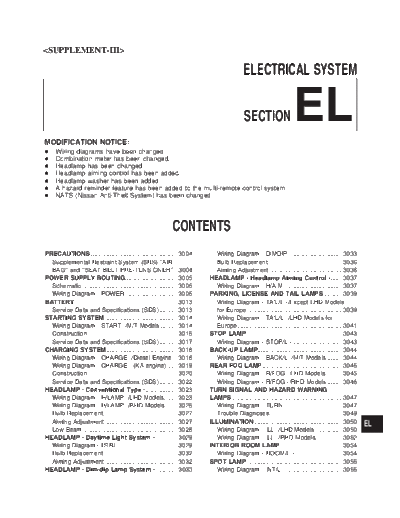
ELECTRICAL SYSTEM MODIFICATION NOTICE: SECTION EL + Wiring diagrams have been changed. + Combination meter has been changed. + Headlamp has been changed. + Headlamp aiming control has been added. + Headlamp washer has been added. + A hazard reminder feature has been added to the multi-remote control system. + NATS (Nissan Anti-Theft System) has been changed. CONTENTS PRECAUTIONS ................................................... 3004 Wiring Diagram - DIMDIP -.............................. 3033 Supplemental Restraint System (SRS) AIR Bulb Replacement............................................ 3036 BAG and SEAT BELT PRE-TENSIONER .. 3004 Aiming Adjustment ........................................... 3036 POWER SUPPLY ROUTING............................... 3005 HEADLAMP - Headlamp Aiming Control -....... 3037 Schematic ........................................................ 3005 Wiring Diagram - H/AIM - ................................ 3037 Wiring Diagram - POWER -............................. 3006 PARKING, LICENSE AND TAIL LAMPS ........... 3039 BATTERY............................................................. 3013 Wiring Diagram - TAIL/L -/Except LHD Models Service Data and Specifications (SDS)........... 3013 for Europe ........................................................ 3039 STARTING SYSTEM ........................................... 3014 Wiring Diagram - TAIL/L -/LHD Models for Wiring Diagram - START -/M/T Models .......... 3014 Europe.............................................................. 3041 Construction ..................................................... 3015 STOP LAMP ........................................................ 3043 Service Data and Specifications (SDS)........... 3017 Wiring Diagram - STOP/L - ............................. 3043 CHARGING SYSTEM .......................................... 3018 BACK-UP LAMP.................................................. 3044 Wiring Diagram - CHARGE -/Diesel Engine ... 3018 Wiring Diagram - BACK/L -/M/T Models ......... 3044 Wiring Diagram - CHARGE - (KA engine) ...... 3019 REAR FOG LAMP ............................................... 3045 Construction ..................................................... 3020 Wiring Diagram - R/FOG -/LHD Models.......... 3045 Service Data and Specifications (SDS)........... 3022 Wiring Diagram - R/FOG -/RHD Models ......... 3046 HEADLAMP - Conventional Type -................... 3023 TURN SIGNAL AND HAZARD WARNING Wiring Diagram - H/LAMP -/LHD Models........ 3023 LAMPS ................................................................. 3047 Wiring Diagram - H/LAMP -/RHD Models ....... 3025 Wiring Diagram - TURN - ................................ 3047 Bulb Replacement............................................ 3027 Trouble Diagnoses........................................... 3049 Aiming Adjustment ........................................... 3027 ILLUMINATION.................................................... 3050 EL Low Beam ........................................................ 3028 Wiring Diagram - ILL -/LHD Models ................ 3050 HEADLAMP - Daytime Light System - ............. 3029 Wiring Diagram - ILL -/RHD Models................ 3052 Wiring Diagram - DTRL -................................. 3029 INTERIOR ROOM LAMP..................................... 3054 Bulb Replacement............................................ 3032 Wiring Diagram - ROOM/L - ............................ 3054 Aiming Adjustment ........................................... 3032 SPOT LAMP ........................................................ 3055 HEADLAMP - Dim-dip Lamp System - ............. 3033 Wiring Diagram - INT/L - ................................. 3055 METER AND GAUGES ....................................... 3056 Wiring Diagram - AUDIO -/RHD Models ......... 3114 System Description .......................................... 3056 AUDIO ANTENNA ............................................... 3115 Combination Meter/With Tachometer .............. 3057 Power Antenna/Wiring Diagram - P/ANT -...... 3115 Combination Meter/Without Tachometer ......... 3058 POWER DOOR MIRROR .................................... 3116 Schematic/With Tachometer............................ 3059 Wiring Diagram - MIRROR -/LHD Models....... 3116 Schematic/Without Tachometer....................... 3060 Wiring Diagram - MIRROR -/RHD Models ...... 3117 Construction ..................................................... 3061 HEATED SEAT .................................................... 3118 Wiring Diagram - METER -/Gasoline Engine Wiring Diagram - H/SEAT - ............................. 3118 with Tachometer .............................................. 3062 POWER WINDOW ............................................... 3120 Wiring Diagram - METER -/Gasoline Engine Schematic/Without Interruption Detection without Tachometer ......................................... 3064 Function ........................................................... 3120 Wiring Diagram - METER -/LHD Diesel Engine Schematic/With Interruption Detection Models with Tachometer.................................. 3065 Function ........................................................... 3121 Wiring Diagram - METER -/RHD Diesel Wiring Diagram - WINDOW -/Without Engine Models with Tachometer ..................... 3067 Interruption Detection Function........................ 3122 Wiring Diagram - METER -/Diesel Engine Wiring Diagram - WINDOW -/With Interruption without Tachometer ......................................... 3069 Detection Function ........................................... 3126 Meter/Gauge Operation and Odo/Trip Meter Trouble Diagnoses/Without Interruption Segment Check in Diagnosis Mode ................ 3070 Detection Function ........................................... 3130 Trouble Diagnoses/With Tachometer .............. 3071 Trouble Diagnoses/With Interruption Detection Trouble Diagnoses/Without Tachometer ......... 3076 Function ........................................................... 3131 WARNING LAMPS .............................................. 3081 POWER DOOR LOCK......................................... 3133 Schematic/With Tachometer............................ 3081 Wiring Diagram - D/LOCK -............................. 3133 Schematic/Without Tachometer....................... 3082 MULTI-REMOTE CONTROL SYSTEM ............... 3135 Wiring Diagram - WARN -/Gasoline Engine System Description .......................................... 3135 with Tachometer .............................................. 3083 MULTI-REMOTE CONTROL SYSTEM ............... 3136 Wiring Diagram - WARN -/Gasoline Engine Wiring Diagram - MULTI - ............................... 3136 without Tachometer ......................................... 3087 Trouble Diagnoses........................................... 3137 Wiring Diagram - WARN -/Diesel Engine with ID Code Entry Procedure ................................ 3139 Tachometer ...................................................... 3091 Remote Controller Battery Replacement......... 3140 Wiring Diagram - WARN -/Diesel Engine THEFT WARNING SYSTEM ............................... 3141 without Tachometer ......................................... 3095 Wiring Diagram - PRWIRE -............................ 3141 A/T INDICATOR................................................... 3100 NATS (Nissan Anti-Theft System) .................... 3142 Wiring Diagram - AT/IND -/RHD Models......... 3100 Component Parts and Harness Connector Wiring Diagram - CHIME -/LHD Models.......... 3101 Location............................................................ 3142 Wiring Diagram - CHIME -/RHD Models ......... 3102 System Description .......................................... 3143 FRONT WIPER AND WASHER .......................... 3103 System Composition ........................................ 3144 Wiring Diagram - WIPER -/Without Intermittent Wiring Diagram - NATS -/LHD Models............ 3145 for Floor-shift.................................................... 3103 Wiring Diagram - NATS -/RHD Diesel Engine Wiring Diagram - WIPER -/Without Intermittent Models.............................................................. 3146 for RHD Column-shift Models.......................... 3106 CONSULT-II..................................................... 3147 HEADLAMP WASHER ........................................ 3108 Trouble Diagnoses........................................... 3149 Wiring Diagram - HLC - ................................... 3108 How to Replace NATS IMMU.......................... 3160 HORN ................................................................... 3109 LOCATION OF ELECTRICAL UNITS................. 3161 Wiring Diagram - HORN -................................ 3109 Engine Compartment ....................................... 3161 CIGARETTE LIGHTER........................................ 3110 Passenger Compartment ................................. 3162 Wiring Diagram - CIGAR -............................... 3110 HARNESS LAYOUT ............................................ 3164 CLOCK................................................................. 3111 Main Harness................................................... 3164 Wiring Diagram - CLOCK -.............................. 3111 Engine Room Harness..................................... 3174 REAR WINDOW DEFOGGER AND MIRROR Engine Control Harness/KA engine................. 3182 DEFOGGER ......................................................... 3112 Engine Control Harness................................... 3184 Wiring Diagram - DEF - ................................... 3112 Engine Harness ............................................... 3185 AUDIO .................................................................. 3113 Alternator Harness ........................................... 3187 Wiring Diagram - AUDIO -/LHD Models.......... 3113 Instrument Harness.......................................... 3189 EL-3002 Chassis Harness and Tail Harness ................. 3190 Rear Door Harness.......................................... 3193 Front Door Harness (LH side) ......................... 3191 WIRING DIAGRAM CODES (CELL CODES)..... 3194 Front Door Harness (RH side)......................... 3192 EL-3003 PRECAUTIONS Supplemental Restraint System (SRS) "AIR BAG" and "SEAT BELT PRE-TENSIONER" The Supplemental Restraint System such as "AIR BAG" and "SEAT BELT PRE-TENSIONER" used along with a seat belt, helps to reduce the risk or severity of injury to the driver and front passenger in a frontal collision. The SRS system composition which is available to NISSAN MODEL D22 is as follows (The com- position varies according to the destination and optional equipment.): Driver air bag module (located in the center of the steering wheel), front passenger air bag module (located on the instrument panel on passenger side), seat belt pre-tensioner, a diagnosis sensor unit, warning lamp, wiring harness and spiral cable. Information necessary to service the system safely is included in the RS section of this Service Manual. WARNING: + To avoid rendering the SRS inoperative, which could increase the risk of personal injury or death in the event of a collision which would result in air bag inflation, all maintenance must be per- formed by an authorized NISSAN dealer. + Improper maintenance, including incorrect removal and installation of the SRS, can lead to per- sonal injury caused by unintentional activation of the system. For removal of Spiral Cable and Air Bag Module, see the RS section. + Do not use electrical test equipment on any circuit related to the SRS unless instructed to in this Service Manual. SRS wiring harnesses can be identified by yellow harness connector. EL-3004 POWER SUPPLY ROUTING Schematic GEL358A EL-3005 POWER SUPPLY ROUTING Wiring Diagram -- POWER -- BATTERY POWER SUPPLY -- IGNITION SWITCH IN ANY POSITION GEL359A EL-3006 POWER SUPPLY ROUTING Wiring Diagram -- POWER -- (Cont'd) GEL360A EL-3007 POWER SUPPLY ROUTING Wiring Diagram -- POWER -- (Cont'd) GEL361A EL-3008 POWER SUPPLY ROUTING Wiring Diagram -- POWER -- (Cont'd) ACCESSORY POWER SUPPLY -- IGNITION SW. IN "ACC" OR "ON" GEL362A EL-3009 POWER SUPPLY ROUTING Wiring Diagram -- POWER -- (Cont'd) IGNITION POWER SUPPLY -- IGNITION SW. IN "ON" AND/OR "START" GEL363A EL-3010 POWER SUPPLY ROUTING Wiring Diagram -- POWER -- (Cont'd) GEL364A EL-3011 POWER SUPPLY ROUTING Wiring Diagram -- POWER -- (Cont'd) GEL365A EL-3012 BATTERY Service Data and Specifications (SDS) Europe Applied model YD25 Standard Type 110D26R Capacity V-AH 12-64 EL-3013 STARTING SYSTEM Wiring Diagram -- START --/M/T Models GEL366A EL-3014 STARTING SYSTEM Construction MEL700P MEL701P EL-3015 STARTING SYSTEM Construction (Cont'd) MEL702P EL-3016 STARTING SYSTEM Service Data and Specifications (SDS) STARTER M2TS0571 M3T29482D S114-348A S114-295B S13-527B Type MITSUBISHI HITACHI Reduction Non-reduction Reduction 2WD 4WD 2WD 4WD Applied model YD25 Z24 ZD30 Standard Standard Option Standard System voltage V 12 No-load Terminal voltage V 11.0 11.5 11.0 Current A Less than 145 Less than 60 Less than 160* More than More than More than More than Revolution rpm More than 3,200 6,500 7,000 6,000 3,300 Minimum diameter of commutator mm (in) 31.4 (1.236) 39.0 (1.535) 35.5 (1.398) Minimum length of brush mm (in) 11.0 (0.433) 11.5 (0.453) 12.0 (0.472) 11.0 (0.433) 13.7 - 25.5 17.7 - 21.6 17.6 - 21.6 28.4 - 34.3 26.7 - 36.1 Brush spring tension N (kg, lb) (1.4 - 2.6, (1.8 - 2.2, (1.8 - 2.2, (2.9 - 3.5, (2.7 - 3.7, 6.0 - 8.2) 3.1 - 5.7) 4.0 - 4.9) 4.0 - 4.9) 6.4 - 7.7) Clearance between bearing metal and Less than 0.2 (0.008) -- armature shaft mm (in) Clearance "!" between pinion front edge 0.5 - 2.0 0.3 - 2.5 -- -- and pinion stopper mm (in) (0.020 - 0.079) (0.012 - 0.098) Movement "!" in height of pinion assembly 0.5 - 2.0 0.3 - 2.0 -- mm (in) (0.020 - 0.079) (0.01 - 0.079) *: Includes magnet switch current. EL-3017 CHARGING SYSTEM Wiring Diagram -- CHARGE --/Diesel Engine GEL368A EL-3018 CHARGING SYSTEM Wiring Diagram -- CHARGE -- (KA engine) GEL238A EL-3019 CHARGING SYSTEM Construction SEL544V MEL704P EL-3020 EL-3021 CHARGING SYSTEM Service Data and Specifications (SDS) ALTERNATOR A5TA5271 A7TA8471 A5TA5372 A3TB0699 LR160-745 LR160-728E Type MITSUBISHI HITACHI Z24 Applied model KA24DE YD25 ZD30 TD27, QD32 Standard Option* Nominal rating V-A 12-70 12-35 12-70 12-90 12-60 Ground polarity Negative Minimum revolution under no- load Less than 1,300 Less than 1,000 (When 13.5V is applied) rpm More than More than More than More than 29/1,300 17/1,300 Hot output current 14/1,300 More than 18/1,300 More than More than (When 13.5V is applied) A/rpm More than 27/2,500 More than 76/2,500 48/2,500 54/2,500 51/2,500 More than More than 88/5,000 57/5,000 Regulated output voltage V 14.1 - 14.7 Minimum length of brush 5.0 (0.20) 6.0 (0.236) mm (in) Brush spring pressure 4.8 - 6.0 (487 - 612, 17.25 - 21.59) 1.0 - 3.43 (102 - 350, 3.60 - 12.34) N (g, oz) Slip ring minimum outer diameter 22.1 (0.870) 26.0 (1.024) mm (in) Rotor (Field coil) resistance 2.5 - 2.9 2.7 - 3.2 2.5 - 2.9 2.1 - 2.5 2.6 2.58 *: Models with power steering and air conditioner EL-3022 HEADLAMP -- Conventional Type -- Wiring Diagram -- H/LAMP --/LHD Models GEL239A EL-3023 HEADLAMP -- Conventional Type -- Wiring Diagram -- H/LAMP --/LHD Models (Cont'd) GEL240A EL-3024 HEADLAMP -- Conventional Type -- Wiring Diagram -- H/LAMP --/RHD Models GEL369A EL-3025 HEADLAMP -- Conventional Type -- Wiring Diagram -- H/LAMP --/RHD Models (Cont'd) GEL370A EL-3026 HEADLAMP -- Conventional Type -- Bulb Replacement The headlamp is a semi-sealed beam type which uses a replace- able halogen bulb. The bulb can be replaced from the engine compartment side without removing the headlamp body. + Grasp only the plastic base when handling the bulb. Never touch the glass envelope. 1. Disconnect the battery cable. 2. Disconnect the harness connector from the back side of the bulb. 3. Pull off the rubber cap. 4. Push and raise retaining pin to loosen it. 5. Remove the headlamp bulb carefully. Do not shake or rotate the bulb when removing it. 6. Install in the reverse order of removal. CAUTION: Do not leave headlamp reflector without bulb for a long period of time. Dust, moisture, smoke, etc. entering head- lamp body may affect the performance of the headlamp. Remove headlamp bulb from the headlamp reflector just before a replacement bulb is installed. GEL452A Aiming Adjustment When performing headlamp aiming adjustment, use an aiming machine, aiming wall screen or headlamp tester. Aimers should be in good repair, calibrated and operated in accordance with respective operation manuals. If any aimer is not available, aiming adjustment can be done as follows: For details, refer to the regulations in your own country. a. Keep all tires inflated to correct pressures. b. Place vehicle and tester on one and same flat surface. SEL596Y c. See that there is no-load in vehicle (coolant, engine oil filled up to correct level and full fuel tank) other than the driver (or equivalent weight placed in driver's position). CAUTION: Be sure aiming switch is set to "0" when performing aiming adjustment on vehicles equipped with headlamp aiming control. SEL597Y EL-3027 HEADLAMP -- Conventional Type -- Low Beam 1. Turn headlamp low beam on. 2. Use adjusting screws to perform aiming adjustment. + First tighten the adjusting screw all the way and then make adjustment by loosening the screw. GEL453A GEL454A + Adjust headlamps so that main axis of light is parallel to center line of body and is aligned with point P shown in illustration. + Figure to the left shows headlamp aiming pattern for driving on right side of road; for driving on left side of road, aiming pattern is reversed. + Dotted lines in illustration show center of headlamp. "H": Horizontal center line of headlamps "WL": Distance between each headlamp center "L": 5,000 mm (196.85 in) "C": 65 mm (2.56 in) SEL254I EL-3028 HEADLAMP -- Daytime Light System -- Wiring Diagram -- DTRL -- GEL371A EL-3029 HEADLAMP -- Daytime Light System -- Wiring Diagram -- DTRL -- (Cont'd) GEL372A EL-3030 HEADLAMP -- Daytime Light System -- Wiring Diagram -- DTRL -- (Cont'd) GEL373A EL-3031 HEADLAMP -- Daytime Light System -- Bulb Replacement For bulb replacement, refer to "HEADLAMP -- Conventional Type --" EL-3027. Aiming Adjustment For aiming adjustment, refer to "HEADLAMP -- Conventional Type --" EL-3027. EL-3032 HEADLAMP -- Dim-dip Lamp System -- Wiring Diagram -- DIMDIP -- GEL374A EL-3033 HEADLAMP -- Dim-dip Lamp System -- Wiring Diagram -- DIMDIP -- (Cont'd) GEL375A EL-3034 HEADLAMP -- Dim-dip Lamp System -- Wiring Diagram -- DIMDIP -- (Cont'd) GEL376A EL-3035 HEADLAMP -- Dim-dip Lamp System -- Bulb Replacement For bulb replacement, refer to EL-3027. Aiming Adjustment For aiming adjustment, refer to EL-3027. EL-3036 HEADLAMP -- Headlamp Aiming Control -- Wiring Diagram -- H/AIM -- GEL377A EL-3037 HEADLAMP -- Headlamp Aiming Control -- Wiring Diagram -- H/AIM -- (Cont'd) GEL378A EL-3038 PARKING, LICENSE AND TAIL LAMPS Wiring Diagram -- TAIL/L --/Except LHD Models for Europe GEL242A EL-3039 PARKING, LICENSE AND TAIL LAMPS Wiring Diagram -- TAIL/L --/Except LHD Models for Europe (Cont'd) GEL460A EL-3040 PARKING, LICENSE AND TAIL LAMPS Wiring Diagram -- TAIL/L --/LHD Models for Europe GEL379A EL-3041 PARKING, LICENSE AND TAIL LAMPS Wiring Diagram -- TAIL/L --/LHD Models for Europe (Cont'd) GEL380A EL-3042 STOP LAMP Wiring Diagram -- STOP/L -- GEL461A EL-3043 BACK-UP LAMP Wiring Diagram -- BACK/L --/M/T Models GEL462A EL-3044 REAR FOG LAMP Wiring Diagram -- R/FOG --/LHD Models GEL383A EL-3045 REAR FOG LAMP Wiring Diagram -- R/FOG --/RHD Models GEL384A EL-3046 TURN SIGNAL AND HAZARD WARNING LAMPS Wiring Diagram -- TURN -- GEL385A EL-3047 TURN SIGNAL AND HAZARD WARNING LAMPS Wiring Diagram -- TURN -- (Cont'd) GEL463A EL-3048 TURN SIGNAL AND HAZARD WARNING LAMPS Trouble Diagnoses Symptom Possible cause Repair order Turn signal and hazard warning 1. Hazard switch 1. Check hazard switch. lamps do not operate. 2. Combination flasher unit 2. Refer to combination flasher unit check. 3. Open in combination flasher unit 3. Check wiring to combination flasher unit for open cir- circuit cuit. Turn signal lamps do not operate 1. 10A fuse 1. Check 10A fuse (No. 10 , located in fuse block). Turn but hazard warning lamps operate. ignition switch ON and verify battery positive voltage 2 is present at terminal V (R/W) of hazard switch. 2. Check hazard switch. 2. Hazard switch 3. Check turn signal switch. 3. Turn signal switch 4. Check G wire between combination flasher unit and 4. Open in turn signal switch circuit turn signal switch for open circuit. Hazard warning lamps do not oper- 1. 10A fuse 1. Check 10A fuse (No. 5 , located in fuse block). ate but turn signal lamps operate. Verify battery positive voltage is present at terminal 3 V (R/Y) of hazard switch. 2. Hazard switch 2. Check hazard switch. 3. Open in hazard switch circuit 3. Check G wire between combination flasher unit and hazard switch for open circuit. Front or side turn signal lamp LH 1. Bulb 1. Check bulb. or RH does not operate. 2. Grounds E6 and E39 2. Check grounds E6 and E39 . Rear turn signal lamp LH or RH 1. Bulb 1. Check bulb. does not operate. 2. Grounds M1 and M54 2. Check grounds M1 and M54 . LH and RH turn indicators do not 1. Ground 1. Check grounds M1 and M54 . operate. LH or RH turn indicator does not 1. Bulb 1. Check bulb in combination meter. operate. EL-3049 ILLUMINATION Wiring Diagram -- ILL --/LHD Models GEL249A EL-3050 ILLUMINATION Wiring Diagram -- ILL --/LHD Models (Cont'd) GEL386A EL-3051 ILLUMINATION Wiring Diagram -- ILL --/RHD Models GEL387A EL-3052 ILLUMINATION Wiring Diagram -- ILL --/RHD Models (Cont'd) GEL388A EL-3053 INTERIOR ROOM LAMP Wiring Diagram -- ROOM/L -- GEL389A EL-3054 SPOT LAMP Wiring Diagram -- INT/L -- GEL252A EL-3055 METER AND GAUGES System Description UNIFIED CONTROL METER +Speedometer, odo/trip meter, tachometer, fuel gauge and water temperature gauge are controlled totally by control unit. + Digital meter is adopted for odo/trip meter.* *The record of the odo meter is kept even if the battery cable is disconnected. The record of the trip meter is erased when the battery cable is disconnected. + Odo/trip meter segment can be checked in diagnosis mode. + Meter/gauge can be checked in diagnosis mode. HOW TO CHANGE THE DISPLAY FOR ODO/TRIP METER SEL253V Note: Turn ignition switch to the "ON" position to operate odo/trip meter. EL-3056 METER AND GAUGES Combination Meter/With Tachometer HEL890B EL-3057 METER AND GAUGES Combination Meter/Without Tachometer HEL891B EL-3058 METER AND GAUGES Schematic/With Tachometer GEL390A EL-3059 METER AND GAUGES Schematic/Without Tachometer GEL391A EL-3060 METER AND GAUGES Construction WITH TACHOMETER SEL450Y WITHOUT TACHOMETER JEL268Y EL-3061 METER AND GAUGES Wiring Diagram -- METER --/Gasoline Engine with Tachometer GEL392A EL-3062 METER AND GAUGES Wiring Diagram -- METER --/Gasoline Engine with Tachometer (Cont'd) GEL256A EL-3063 METER AND GAUGES Wiring Diagram -- METER --/Gasoline Engine without Tachometer GEL397A EL-3064 METER AND GAUGES Wiring Diagram -- METER --/LHD Diesel Engine Models with Tachometer GEL393A EL-3065 METER AND GAUGES Wiring Diagram -- METER --/LHD Diesel Engine Models with Tachometer (Cont'd) GEL394A EL-3066 METER AND GAUGES Wiring Diagram -- METER --/RHD Diesel Engine Models with Tachometer GEL395A EL-3067 METER AND GAUGES Wiring Diagram -- METER --/RHD Diesel Engine Models with Tachometer (Cont'd) GEL396A EL-3068 METER AND GAUGES Wiring Diagram -- METER --/Diesel Engine without Tachometer GEL398A EL-3069 METER AND GAUGES Meter/Gauge Operation and Odo/Trip Meter Segment Check in Diagnosis Mode DIAGNOSIS FUNCTION + Odo/trip meter segment can be checked in diagnosis mode. + Meters/gauges can be checked in diagnosis mode. HOW TO ALTERNATE DIAGNOSIS MODE 1. Turn ignition switch to ON and change odo/trip meter to "TRIP A" or "TRIP B". 2. Turn ignition switch to OFF. 3. Turn ignition switch to ON when pushing odo/trip meter switch. 4. Confirm that trip meter indicates "000.0". 5. Push odo/trip meter switch more than three times within 5 seconds. 6. All odo/trip meter segments should be turned on. NOTE: If some segments are not turned on, unified meter control unit with odo/trip meter should be replaced. At this point, the unified control meter is turned to diagnosis mode. SEL110V 7. Push odo/trip meter switch. Indication of each meter/gauge should be as shown left during pushing odo/trip meter switch if it is no malfunctioning. NOTE: It takes about a few seconds for indication of fuel gauge to become stable. SEL111VA SEL427W EL-3070 METER AND GAUGES Trouble Diagnoses/With Tachometer PRELIMINARY CHECK SEL269Y *1:Meter/Gauge Operation and Odo/ *2:POWER SUPPLY AND GROUND *3:Symptom Chart (EL-3071) Trip Meter Segment Check in Diagno- CIRCUIT CHECK (EL-3072) sis Mode (EL-3070) SYMPTOM CHART Symptom Possible causes Repair order 1. Check the sensor for malfunctioning One of speedometer/fuel gauge/water meter/gauge. INSPECTION/VEHICLE temp. gauge is malfunctioning. 1. Sensor signal SPEED SIGNAL (Refer to EL section - Vehicle speed signal "Vehicle speed signal" in original Ser- - Fuel gauge vice Manual.) - Water temp. gauge INSPECTION/FUEL LEVEL SENSOR Multiple meter/gauge are malfunction- 2. Unified meter control unit UNIT INSPECTION/THERMAL ing. (except odo/trip meter) TRANSMITTER 2. Replace unified meter control unit. Before starting trouble diagnoses below, perform PRELIMINARY CHECK, EL-3071. EL-3071 METER AND GAUGES Trouble Diagnoses/With Tachometer (Cont'd) POWER SUPPLY AND GROUND CIRCUIT CHECK Power supply circuit check Terminals Ignition switch position @ OFF ACC ON Battery Battery Battery V (R/G) 18 Ground voltage voltage voltage Battery V (W/B) 17 Ground 0V 0V voltage SEL404Y If NG, check the following. + 10A fuse [No. 11 , located in fuse block (J/B)] + 10A fuse [No. 6 , located in fuse block (J/B)] + Harness for open or short between fuse and combination meter Ground circuit check Terminals Continuity V - Ground (B) 24 Yes SEL405Y EL-3072 METER AND GAUGES Trouble Diagnoses/With Tachometer (Cont'd) INSPECTION/VEHICLE SPEED SENSOR Without ABS for the Middle East and Except for the Middle East CHECK VEHICLE SPEED SENSOR OK Vehicle speed sensor is c OUTPUT. OK. 1. Remove vehicle speed sensor from transmission. 2. Check voltage between combination meter connector N4 terminals V 22 (W) and V (R) while quickly turning 23 speed sensor pinion. Voltage: Approx. 0.5V NG . CHECK VEHICLE SPEED SENSOR. NG Replace vehicle speed c Check resistance between vehicle speed sensor. 1 sensor connector E223 terminals V (W) and V2 (R). SEL406Y Resistance: Approx. 250 OK . Check harness for open or short between combination meter and vehicle speed sensor. SEL447VA INSPECTION/ENGINE REVOLUTION SIGNAL CHECK ECM OUTPUT. OK Engine revolution signal is c 1. Start engine. OK. 2. Check voltage between combination meter terminal V (W) and ground at 21 idle and 2,000 rpm. Higher rpm = Higher voltage Lower rpm = Lower voltage Voltage should change with rpm. SEL407Y NG . Check the following. + Harness for open or short between ECM and combination meter EL-3073 METER AND GAUGES Trouble Diagnoses/With Tachometer (Cont'd) INSPECTION/FUEL LEVEL SENSOR UNIT CHECK GROUND CIRCUIT FOR FUEL NG Repair harness or connec- c LEVEL SENSOR UNIT. tor. Check harness continuity between fuel level sensor unit connector C3 terminal 1 V (B) and ground. Continuity should exist. OK SEL639Y . CHECK GAUGE UNITS. NG Repair or replace. c Refer to EL section "FUEL LEVEL SEN- Refer to FE section of Ser- SOR UNIT" in original Service Manual vice Manual Pub. No. Pub. No. SM7E-0D22G1. SM7E-0D22G1. OK . CHECK HARNESS FOR OPEN OR NG Repair harness or connec- c SHORT. tor. 1. Disconnect combination connector and fuel level sensor unit connector. 2. Check continuity between combination meter terminal V (Y/G) and fuel level 20 sensor unit connector C3 terminal 3 V (Y/G). Continuity should exist. 3. Check continuity between combination meter terminal V (Y/G) and ground. 20 Continuity should not exist. OK . SEL409Y Fuel level sensor unit is OK. EL-3074 METER AND GAUGES Trouble Diagnoses/With Tachometer (Cont'd) INSPECTION/THERMAL TRANSMITTER NG CHECK THERMAL TRANSMITTER. c Repair or replace. Refer to EL section "THERMAL TRANS- MITTER" in original Service Manual Pub. No. SM7E-0D22G1. OK . NG CHECK HARNESS FOR OPEN OR c Repair harness or connec- SHORT. tor. 1. Disconnect combination connector and thermal transmitter connector. 2. Check continuity between combination meter terminal V (Y/R) and thermal 19 transmitter connector E9 , M209 , E209 1 terminal V . Continuity should exist. 3. Check continuity between combination meter terminal V (Y/R) and ground. 19 Continuity should not exist. OK . Thermal transmitter is OK. SEL410Y EL-3075 METER AND GAUGES Trouble Diagnoses/Without Tachometer PRELIMINARY CHECK SEL269Y *1:Meter/Gauge Operation and Odo/ *2:POWER SUPPLY AND GROUND *3:Symptom Chart (EL-3076) Trip Meter Segment Check in Diagno- CIRCUIT CHECK (EL-3077) sis Mode (EL-3070) SYMPTOM CHART Symptom Possible causes Repair order 1. Check the sensor for malfunctioning One of speedometer/fuel gauge/water meter/gauge. INSPECTION/VEHICLE temp. gauge is malfunctioning. 1. Sensor signal SPEED SIGNAL (Refer to EL section - Vehicle speed signal "Vehicle speed signal" in original Ser- - Fuel gauge vice Manual.) - Water temp. gauge INSPECTION/FUEL LEVEL SENSOR Multiple meter/gauge are malfunction- 2. Unified meter control unit UNIT INSPECTION/THERMAL ing. (except odo/trip meter) TRANSMITTER 2. Replace unified meter control unit. Before starting trouble diagnoses below, perform PRELIMINARY CHECK, EL-3076. EL-3076 METER AND GAUGES Trouble Diagnoses/Without Tachometer (Cont'd) POWER SUPPLY AND GROUND CIRCUIT CHECK Power supply circuit check Terminals Ignition switch position @ OFF ACC ON Battery Battery Battery V (R/G) 21 Ground voltage voltage voltage Battery SEL618Y V (W/B) 22 Ground 0V 0V voltage If NG, check the following. + 10A fuse [No. 6 , located in fuse block (J/B)] + 10A fuse [No. 11 , located in fuse block (J/B)] + Harness for open or short between fuse and combination meter Ground circuit check Terminals Continuity V - Ground (B) 23 Yes SEL619Y EL-3077 METER AND GAUGES Trouble Diagnoses/Without Tachometer (Cont'd) INSPECTION/VEHICLE SPEED SENSOR Without ABS for the Middle East and Except for the Middle East CHECK VEHICLE SPEED SENSOR OK Vehicle speed sensor is c OUTPUT. OK. 1. Remove vehicle speed sensor from transmission. 2. Check voltage between combination meter connector N10 terminals V 24 (W) and V (R) while quickly turning 37 speed sensor pinion. Voltage: Approx. 0.5V NG . CHECK VEHICLE SPEED SENSOR. NG Replace vehicle speed c Check resistance between vehicle speed sensor. 1 sensor connector E223 terminals V (W) SEL620Y 2 and V (R). Resistance: Approx. 250 OK . Check harness for open or short between combination meter and vehicle speed sensor. SEL447VA EL-3078 METER AND GAUGES Trouble Diagnoses/Without Tachometer (Cont'd) INSPECTION/FUEL LEVEL SENSOR UNIT CHECK GROUND CIRCUIT FOR FUEL NG Repair harness or connec- c LEVEL SENSOR UNIT. tor. Check harness continuity between fuel level sensor unit connector C3 terminal 1 V (B) and ground. Continuity should exist. SEL639Y OK . CHECK GAUGE UNITS. NG Repair or replace. c Refer to EL section "FUEL LEVEL SEN- Refer to FE section of Ser- SOR UNIT" in original Service Manual vice Manual Pub. No. Pub. No. SM7E-0D22G1. SM7E-0D22G1. OK . CHECK HARNESS FOR OPEN OR NG Repair harness or connec- c SHORT. tor. 1. Disconnect combination connector and fuel level sensor unit connector. 2. Check continuity between combination meter terminal V (Y/G) and fuel level 35 sensor unit connector C3 terminal 3 V (Y/G). Continuity should exist. 3. Check continuity between combination meter terminal V (Y/G) and ground. 35 Continuity should not exist. SEL621Y OK . Fuel level sensor unit is OK. EL-3079 METER AND GAUGES Trouble Diagnoses/Without Tachometer (Cont'd) INSPECTION/THERMAL TRANSMITTER NG CHECK THERMAL TRANSMITTER. c Repair or replace. Refer to EL section "THERMAL TRANS- MITTER" in original Service Manual Pub. No. SM7E-0D22G1. OK . NG CHECK HARNESS FOR OPEN OR c Repair harness or connec- SHORT. tor. 1. Disconnect combination connector and thermal transmitter connector. 2. Check continuity between combination meter terminal V (Y/R) and thermal 34 transmitter connector E9 , M209 , E209 1 terminal V . Continuity should exist. 3. Check continuity between combination meter terminal V (Y/R) and ground. 34 Continuity should not exist. OK . SEL622Y Thermal transmitter is OK. EL-3080 WARNING LAMPS Schematic/With Tachometer GEL399A EL-3081 WARNING LAMPS Schematic/Without Tachometer GEL408A EL-3082 WARNING LAMPS Wiring Diagram -- WARN --/Gasoline Engine with Tachometer GEL400A EL-3083 WARNING LAMPS Wiring Diagram -- WARN --/Gasoline Engine with Tachometer (Cont'd) GEL401A EL-3084 WARNING LAMPS Wiring Diagram -- WARN --/Gasoline Engine with Tachometer (Cont'd) GEL402A EL-3085 WARNING LAMPS Wiring Diagram -- WARN --/Gasoline Engine with Tachometer (Cont'd) GEL403A EL-3086 WARNING LAMPS Wiring Diagram -- WARN --/Gasoline Engine without Tachometer GEL409A EL-3087 WARNING LAMPS Wiring Diagram -- WARN --/Gasoline Engine without Tachometer (Cont'd) GEL410A EL-3088 WARNING LAMPS Wiring Diagram -- WARN --/Gasoline Engine without Tachometer (Cont'd) GEL411A EL-3089 WARNING LAMPS Wiring Diagram -- WARN --/Gasoline Engine without Tachometer (Cont'd) GEL412A EL-3090 WARNING LAMPS Wiring Diagram -- WARN --/Diesel Engine with Tachometer GEL404A EL-3091 WARNING LAMPS Wiring Diagram -- WARN --/Diesel Engine with Tachometer (Cont'd) GEL405A EL-3092 WARNING LAMPS Wiring Diagram -- WARN --/Diesel Engine with Tachometer (Cont'd) GEL406A EL-3093 WARNING LAMPS Wiring Diagram -- WARN --/Diesel Engine with Tachometer (Cont'd) GEL407A EL-3094 WARNING LAMPS Wiring Diagram -- WARN --/Diesel Engine without Tachometer GEL413A EL-3095 WARNING LAMPS Wiring Diagram -- WARN --/Diesel Engine without Tachometer (Cont'd) GEL414A EL-3096 WARNING LAMPS Wiring Diagram -- WARN --/Diesel Engine without Tachometer (Cont'd) GEL415A EL-3097 WARNING LAMPS Wiring Diagram -- WARN --/Diesel Engine without Tachometer (Cont'd) GEL416A EL-3098 WARNING LAMPS Wiring Diagram -- WARN --/Diesel Engine without Tachometer (Cont'd) GEL417A EL-3099 A/T INDICATOR Wiring Diagram -- AT/IND --/RHD Models GEL418A EL-3100 A/T INDICATOR Wiring Diagram -- CHIME --/LHD Models LIGHT WARNING BUZZER GEL420A EL-3101 A/T INDICATOR Wiring Diagram -- CHIME --/RHD Models LIGHT WARNING BUZZER GEL421A EL-3102 FRONT WIPER AND WASHER Wiring Diagram -- WIPER --/Without RHD MODELS KA ENGINE Intermittent for Floor-shift GEL423A EL-3103 FRONT WIPER AND WASHER Wiring Diagram -- WIPER --/Without Intermittent for Floor-shift (Cont'd) RHD MODELS GEL425A EL-3104 FRONT WIPER AND WASHER Wiring Diagram -- WIPER --/Without Intermittent for Floor-shift (Cont'd) GEL426A EL-3105 FRONT WIPER AND WASHER Wiring Diagram -- WIPER --/Without Intermittent for RHD Column-shift Models GEL427A EL-3106 FRONT WIPER AND WASHER Wiring Diagram -- WIPER --/Without Intermittent for RHD Column-shift Models (Cont'd) GEL428A EL-3107 HEADLAMP WASHER Wiring Diagram -- HLC -- GEL429A EL-3108 HORN Wiring Diagram -- HORN -- GEL274A EL-3109 CIGARETTE LIGHTER Wiring Diagram -- CIGAR -- GEL275A EL-3110 CLOCK Wiring Diagram -- CLOCK -- GEL430A EL-3111 REAR WINDOW DEFOGGER AND MIRROR DEFOGGER Wiring Diagram -- DEF -- GEL431A EL-3112 AUDIO Wiring Diagram -- AUDIO --/LHD Models GEL435A EL-3113 AUDIO Wiring Diagram -- AUDIO --/RHD Models GEL437A EL-3114 AUDIO ANTENNA Power Antenna/Wiring Diagram -- P/ANT -- GEL438A EL-3115 POWER DOOR MIRROR Wiring Diagram -- MIRROR --/LHD Models GEL439A EL-3116 POWER DOOR MIRROR Wiring Diagram -- MIRROR --/RHD Models GEL440A EL-3117 HEATED SEAT Wiring Diagram -- H/SEAT -- GEL441A EL-3118 HEATED SEAT Wiring Diagram -- H/SEAT -- (Cont'd) GEL442A EL-3119 POWER WINDOW Schematic/Without Interruption Detection Function GEL281A EL-3120 POWER WINDOW Schematic/With Interruption Detection Function GEL286A EL-3121 POWER WINDOW Wiring Diagram -- WINDOW --/Without Interruption Detection Function GEL282A EL-3122 POWER WINDOW Wiring Diagram -- WINDOW --/Without Interruption Detection Function (Cont'd) GEL283A EL-3123 POWER WINDOW Wiring Diagram -- WINDOW --/Without Interruption Detection Function (Cont'd) GEL284A EL-3124 POWER WINDOW Wiring Diagram -- WINDOW --/Without Interruption Detection Function (Cont'd) GEL285A EL-3125 POWER WINDOW Wiring Diagram -- WINDOW --/With Interruption Detection Function GEL287A EL-3126 POWER WINDOW Wiring Diagram -- WINDOW --/With Interruption Detection Function (Cont'd) GEL288A EL-3127 POWER WINDOW Wiring Diagram -- WINDOW --/With Interruption Detection Function (Cont'd) GEL289A EL-3128 POWER WINDOW Wiring Diagram -- WINDOW --/With Interruption Detection Function (Cont'd) GEL290A EL-3129 POWER WINDOW Trouble Diagnoses/Without Interruption Detection Function Symptom Possible cause Repair order None of the power windows can be 1. 40A fusible link and circuit 1. Check 40A fusible link (letter c , located in fusible link operated using any switch. breaker-1 and fuse box) and circuit breaker-1, located in fuse block. Turn ignition switch "ON" and verify battery posi- 1 tive voltage is present at terminal V of power window 5 main switch and terminal V of sub-switch. 2. Grounds M1 and M54 2. Check grounds M1 and M54 . 3. Power window relay 3. Check power window relay. 4. Open/short in power window 4. Check harness between power window relay and main switch circuit power window main switch for open/short circuit. Driver side power window cannot be 1. Driver side power window regula- 1. Check harness between power window main switch operated but other windows can be tor circuit and power window regulator for open or short circuit. operated. 2. Driver side power window regula- 2. Check driver side power window regulator. tor One or some of power window 1. Power window sub-switch 1. Check power window sub-switch. except driver side power window 2. Passenger side power window 2. Check power window regulator of malfunctioning cannot be operated. regulator power window. 3. Power window main switch 3. Check power window main switch. 4. Power window circuit 4-1. Check harnesses between power window main switch and power window sub-switch for open/short circuit. 4-2. Check harnesses between power window sub- switch an
◦ Jabse Service Manual Search 2026 ◦ Jabse Pravopis ◦ onTap.bg ◦ Other service manual resources online : Fixya ◦ eServiceinfo