Service Manuals, User Guides, Schematic Diagrams or docs for : . Car Manuals Subaru Forester 1999-2004 Approved Subaru Forester 1999-2000 AUTOMATIC TRANSMISSION MSA5T0128A34690

<< Back | Home

Most service manuals and schematics are PDF files, so You will need Adobre Acrobat Reader to view : Acrobat Download Some of the files are DjVu format. Readers and resources available here : DjVu Resources
For the compressed files, most common are zip and rar. Please, extract files with Your favorite compression software ( WinZip, WinRAR ... ) before viewing. If a document has multiple parts, You should download all, before extracting.
Good luck. Repair on Your own risk. Make sure You know what You are doing.


Image preview - the first page of the document
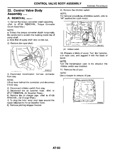
MSA5T0128A34690


>> Download MSA5T0128A34690 documenatation <<

Text preview - extract from the document
                                  CONTROL VALVE BODY ASSEMBLY
                                                                                        Automatic Transmission

22. Control Valve Body                                  9) Remove the inhibitor switch .

Assembly S5,o593                                        NOTE :
                                                        For removal procedures of inhibitor switch, refer to
A : REMOVAL          S5f0593A18                         "AT" sections for each model .
1) Extract the torque converter clutch assembly.

NOTE :
  Extract the torque converter clutch horizontally.
Be careful not to scratch the bushing inside the oil
pump shaft.
  Note that oil pump shaft also comes out .
2) Remove the input shaft.
                                                                                                  B3M1087Bj

                                                           (A)   Inhibitor switch

                                                       10) Prepare a block of wood. Turn the transmis-
                                                       sion case over, and support it with the block of
                                                       wood .
                                                       NOTE:
                                                       Turn the transmission case in the direction the
                                                       inhibitor switch was installed.
                                                       11) Remove the oil pan .
                                                       NOTE :
3) Disconnect transmission harness connector
from stay.                                             Use a scraper to remove oil pan.

NOTE:
Lift-up lever behind the connector and disconnect
it from stay.
4) Disconnect inhibitor switch from stay.
5) Disconnect the air breather hose . 
6) Remove the oil charger pipe .                                                SOD
7) To plug the hole, wrap vinyl tape around the
nipple attached to the air breather hose .                                                         B3M2022 1

8) Remove pitching stopper bracket.


                                                 AT83
                               CONTROL VALVE BODY ASSEMBLY
Automatic Transmission

12) Disconnect the harness connectors for the       B : INSTALLATION 55,059
solenoids, duty solenoids, ATF temperature sensor
and the ground cord .                               1) Set the select lever in range "N".
                                                    2) Align the groove of the manual valve to the
                                                    protrusion of the manual lever, and then install the
                                                    control valve body assembly.
                                                    Tightening torque:
                                                        8 N~m (0 .8 kgf-m, 5.8 ft-Ib)


   (A) Lock-up duty solenoid (Blue)
   (B) Low clutch timing solenoid (Gray)
   (C) Line pressure duty solenoid (Red)
   (D) Shift solenoid 2 (Yellow)
   (E) Shift solenoid 1 (Green)
   (F) 2-4 brake timing solenoid (Black)
                                                       (A)   Short bolts
   (G) 2-4 brake duty solenoid (Red)
                                                       (B)   Long bolts
   (H) ATF temperature sensor
   (I) Transfer duty solenoid (Brown)               3) Tighten the valve body to the specified torque .
   (J) Transmission ground
                                                    CAUTION :
13) Remove the control valve body assembly .        Tighten the control valve mounting            bolts
                                                    evenly.
                                                    Tightening Torque:
                                                        8 N~m (0.8 kgf-m, 5.8 ft-Ib)
                                                    4) Connect all connectors .


                                                       (A)   Lock-up duty solenoid (Blue)
                                                       (B)   Low clutch timing solenoid (Gray)
                                                       (C)   Line pressure duty solenoid (Red)
                                                       (D)   Shift solenoid 2 (Yellow)
                                                       (E)   Shift solenoid 1 (Green)
                                                       (F)   2-4 brake timing solenoid (Black)
                                                       (G)   2-4 brake duty solenoid (Red)
                                                       (H)   ATF temperature sensor
                                                       (I)   Transfer duty solenoid (Brown)
                                                       (J)   Transmission ground


                                               AT84
                                     CONTROL VALVE BODY ASSEMBLY
                                                                                                  Automatic Transmission

 5) Attach the magnet at the specified position               10) Install inhibitor switch and adjust the inhibitor
                                                              switch by referring to Supplement AT section.
                                                              11) Insert inhibitor switch and transmission con-
                     o                                        nector into stay.
          (B)                o
          o
                                                                            (B
                                                                                                          A)


     \O          ~

                     \   \       \        B3M 11058                                          l-\                 /


    (A)    Magnet
    (B)    Oil pan
                                                                                                               83M1054A

6) Apply proper amount of liquid gasket to the                   (A)   Transmission harness
entire oil pan mating surface.                                   (B)   Inhibitor switch harness
Liquid gasket:
     THREE BOND 1217B                                         12) Insert the input shaft while turning lightly by
                                                              hand.
                                                              CAUTION :
                                                              Be careful not to damage the bushing.
                                                              Normal protrusion A:
                                                                  50 - 55 mm (1.97 - 2.17 in)


   (A)     THREE BOND (Part No . 12178)

7) Install the oil pan to the transmission case
assembly, and secure with 20 bolts.
NOTE :
Tighten the bolts evenly .
                                                          13) Install the torque converter clutch assembly.
Tightening torque:                                        

                                                          C : DISASSEMBLY                    5510593A06


                                                          1) Remove oil strainer from lower control valve
                                                          body.
                             U
                             0

                                          B3M2022

8) Turn over the transmission case to its original
position.
9) Install air breather hose . 

                                                      AT 85
                                CONTROL VALVE BODY ASSEMBLY
Automatic Transmission

2) Remove the duty solenoids, solenoids and sen-                                                        o 00              0
sor from the lower valve body.                                         Sp p o              ao .               c
                                                                                                                      r
                                                                            o                            o
                                                                                                       o 0        o   do
                                                                                    o     ~


◦ Jabse Service Manual Search 2024 ◦ Jabse PravopisonTap.bg ◦ Other service manual resources online : FixyaeServiceinfo