Service Manuals, User Guides, Schematic Diagrams or docs for : . Car Manuals Subaru Forester 1999-2004 Approved Subaru Forester 1999-2000 ENGINE SECTION Engine MSA5T0122A27576

<< Back | Home

Most service manuals and schematics are PDF files, so You will need Adobre Acrobat Reader to view : Acrobat Download Some of the files are DjVu format. Readers and resources available here : DjVu Resources
For the compressed files, most common are zip and rar. Please, extract files with Your favorite compression software ( WinZip, WinRAR ... ) before viewing. If a document has multiple parts, You should download all, before extracting.
Good luck. Repair on Your own risk. Make sure You know what You are doing.


Image preview - the first page of the document
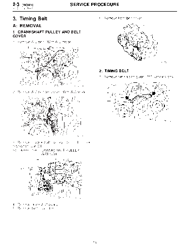
MSA5T0122A27576


>> Download MSA5T0122A27576 documenatation <<

Text preview - extract from the document
2-3   [W3A1]                       SERVICE PROCEDURE
3. Timing Belt


3. Timing Belt                                            6) Remove front belt cover.

A: REMOVAL
1. CRANKSHAFT PULLEY AND BELT
COVER
1) Remove A/C belt. (With A/C model)


                                                                                                B2M2587


                                                          2. TIMING BELT
                                                          1) Remove timing belt guide. (MT vehicles only)

                                        B2M2584

2) Remove A/C belt tensioner. (With A/C model)


                                                                                                S2M0294


                                        B2M2585

3) Remove crankshaft pulley bolt. To          lock
crankshaft, use ST.
ST 499977100 CRANKSHAFT PULLEY
                  WRENCH


                                       S2M1860A

4) Remove crankshaft pulley.
5) Remove belt cover (LH).


                                                     14
                                     SERVICE PROCEDURE                                       [W3A2] 2-3
                                                                                             3. Timing Belt


2) If alignment mark (a) and/or arrow mark (which           (2) Using white paint, put alignment and/or
indicates rotation direction) on timing belt fade           arrow marks on timing belts in relation to the
away, put new marks before removing timing belt             crank sprocket and cam sprockets.
as shown in procedures below.
   (1) Turn crankshaft using ST. Align mark (a) of
   sprocket to cylinder block notch (b) and ensure
   that right side cam sprocket mark (c), cam cap
   and cylinder head matching surface (d) and/or
   left side cam sprocket mark (e) and belt cover
   notch (f) are properly adjusted.
ST 499987500 CRANKSHAFT SOCKET


                                                                                                B2M2591


                                                          Specified data:
                                                              Z1: 44 tooth length
                                                              Z2: 40.5 tooth


                                      S2M1861A


                                                                                               B2M2592A

                                                          3) Remove belt idler (No. 2).
                                                          4) Remove belt idler No. 2.


                                                                                                S2M1008

                                                          5) Remove timing belt.
                                      S2M1007C


                                                                                                B2M2594


                                                     15
2-3   [W3A3]                       SERVICE PROCEDURE
3. Timing Belt


3. BELT IDLER AND AUTOMATIC BELT                        3) Remove camshaft sprocket No. 1. To lock
TENSION ADJUSTER ASSEMBLY                               camshaft, using ST.
                                                        ST 499207400 CAMSHAFT SPROCKET
1) Remove belt idler (No. 1).
                                                                         WRENCH


                                      B2M2596
                                                                                           S2M1863A

2) Remove automatic belt tension adjuster assem-        4) Remove crankshaft sprocket.
bly.


                                                                                            S2M0414
                                      H2M2375
                                                        5) Remove belt cover No. 2 (LH).
4. CAMSHAFT AND CRANKSHAFT                              6) Remove belt cover No. 2 (RH).
SPROCKET                                                CAUTION:
1) Remove camshaft position sensor.                     Do not damage or lose the seal rubber when
2) Remove camshaft sprocket No. 2. To lock              removing belt covers.
camshaft, use ST.
ST 499207100 CAMSHAFT SPROCKET
                  WRENCH


                                                                                            B2M2601


                                     S2M1862A


                                                   16
                                      SERVICE PROCEDURE                                            [W3B4] 2-3
                                                                                                   3. Timing Belt


7) Remove tensioner bracket.                                   (1) Slowly press the adjuster rod down to the
                                                               end surface of the cylinder. Repeat this motion
                                                               2 or 3 times.
                                                               (2) With the adjuster rod moved all the way up,
                                                               apply a pressure of 294 N (30 kg, 66 lb) to it.
                                                               Check adjuster rod stiffness.
                                                               (3) If the adjuster rod is not stiff and moves
                                                               down, replace the automatic belt tension
                                                               adjuster assembly with a new one.
                                                            CAUTION:


◦ Jabse Service Manual Search 2024 ◦ Jabse PravopisonTap.bg ◦ Other service manual resources online : FixyaeServiceinfo