Service Manuals, User Guides, Schematic Diagrams or docs for : . Car Manuals Subaru Forester 1999-2004 Approved Subaru Forester 1999-2000 TRANSMISSION AND DIFFERENTIAL SECTION Transmission Control System MSA5T0124A27724

<< Back | Home

Most service manuals and schematics are PDF files, so You will need Adobre Acrobat Reader to view : Acrobat Download Some of the files are DjVu format. Readers and resources available here : DjVu Resources
For the compressed files, most common are zip and rar. Please, extract files with Your favorite compression software ( WinZip, WinRAR ... ) before viewing. If a document has multiple parts, You should download all, before extracting.
Good luck. Repair on Your own risk. Make sure You know what You are doing.


Image preview - the first page of the document
MSA5T0124A27724


>> Download MSA5T0124A27724 documenatation <<

Text preview - extract from the document
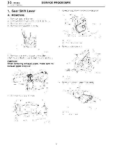
3-3  [W1A0]                           SERVICE PROCEDURE
1. Gear Shift Lever


1. Gear Shift Lever                                    7) Remove stay from transmission bracket.

A: REMOVAL
1)   Remove   gear shift knob.
2)   Remove   front cover. 
3)   Remove   console boot.
4)   Remove   boot plate from body.


                                                                                             B3M1823A

                                                          (A)   Stay
                                                          (B)   Transmission bracket

                                                       8) Remove rod from joint.

                                         B3M0615

5) Remove rear exhaust pipe and muffler.
 and 
CAUTION:
When removing exhaust pipes, make sure no
exhaust pipes drop out.


                                                                                             B3M1824A

                                                          (A)   Stay
                                                          (B)   Rod

                                                       9) Remove cushion rubber from body.


                                         B2M0055

6) Remove heat shield cover.


                                                                                             B3M1825A

                                                          (A)   Rod
                                                          (B)   Cushion rubber


                                         B3M1605


                                                   4
                                    SERVICE PROCEDURE                                    [W1B0] 3-3
                                                                                     1. Gear Shift Lever


10) Remove joint and then extract straight pin.       2) Remove rod from gear shift lever.


                                      B3M1826A                                               B3M1828A

   (A)   Joint                                           (A)   Rod
   (B)   Straight pin                                    (B)   Gear shift lever
                                                         (C)   Stay
11) Remove gear shift lever.
                                                      3) Remove snap ring from bush D, then discon-
                                                      nect stay.


                                       B3M1827


                                                                                             B3M0619B
B: DISASSEMBLY
                                                         (A)   Snap ring
1) Disassemble locking wire.                             (B)   Bush D
                                                         (C)   Boot

                                                      4) Remove boot from gear shift lever.
                                                      5) Remove bush and cushion rubber from stay.


                                      B3M0617C

   (A)   Locking wire
   (B)   Stay

                                                                                             B3M0830D

                                                         (A)   Bush B
                                                         (B)   Stay
                                                         (C)   Cushion rubber


                                                  5
3-3  [W1C0]                         SERVICE PROCEDURE
1. Gear Shift Lever


6) Remove O-ring, then disconnect bush D.               C: INSPECTION
                                                        Check each part (bush A, cushion rubber, spacer,
                                                        boot, stay and rod, etc.) for deformation, damage
                                                        and wear. Repair or replace any defective part.
                                                        Determine defective parts by comparing with new
                                                        parts.


                                      B3M0620B

   (A)   O-ring
   (B)   Bush D

7) Draw out straight pin, then remove bush C from
gear shift lever.


                                      B3M0621B
                                                                                              B3M1765A
   (A)   Straight pin
   (B)   Bush C                                            (A)   Bush A
                                                           (B)   Cushion rubber
                                                           (C)   Spacer
                                                           (D)   Boot
                                                           (E)   Stay
                                                           (F)   Rod

                                                        D: ASSEMBLY
                                                        1) Clean all parts before assembly.
                                                        2) Mount the bush B and cushion rubber on the
                                                        stay.


                                                                                              B3M0830C

                                                           (A)   Bush B
                                                           (B)   Cushion rubber


                                                    6
                                       SERVICE PROCEDURE                                      [W1D0] 3-3
                                                                                          1. Gear Shift Lever


3) Mount each part; boot, O-ring, bush A, spacer,        6) Tighten with locking wire to the extent that the
bush B, bush D and straight pin on the gear shift        boot will not come off.
lever.                                                   CAUTION:
CAUTION:                                                 Always use new locking wire.


◦ Jabse Service Manual Search 2024 ◦ Jabse PravopisonTap.bg ◦ Other service manual resources online : FixyaeServiceinfo