Service Manuals, User Guides, Schematic Diagrams or docs for : . Car Manuals Subaru Forester 1999-2004 Approved Subaru Forester 2004 2 - Engine Section (H4SO) Lubrication Oil Pressure System
<< Back | HomeMost service manuals and schematics are PDF files, so You will need Adobre Acrobat Reader to view : Acrobat Download Some of the files are DjVu format. Readers and resources available here : DjVu Resources
For the compressed files, most common are zip and rar. Please, extract files with Your favorite compression software ( WinZip, WinRAR ... ) before viewing. If a document has multiple parts, You should download all, before extracting.
Good luck. Repair on Your own risk. Make sure You know what You are doing.
Image preview - the first page of the document
>> Download Oil Pressure System documenatation <<
Text preview - extract from the document
                                                                     OIL PRESSURE SYSTEM
                                                                                                                                                               LUBRICATION

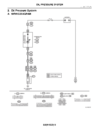
2. Oil Pressure System
A: WIRING DIAGRAM
                                                                                                                                BATTERY
                                                                                                 No.14


                                                      B36


                                                5
                                                       i1

                                                B9
                              WARNING LIGHT
                              OIL PRESSURE


                                                               COMBINATION
                                                                 METER

                                                               A:    i12

                                                               B:    i10
                                                A3


                                                      i3
                                                14


                                                      B38


                                                      TB
                                                      B100
                                                6


                                                       F2


                                                      NA       TB
                                              TB NA
                                              14 5


                                                      B22      F61

                                                       E3      E2


                                                                                              NA    :NON-TURBO MODEL
                                                             E11                              TB    :TURBO MODEL


                                                                                                                                                   E


                                OIL PRESSURE
                                   SWITCH


         A:    i12    (GREEN)                                                B:    i10    (GREEN)
                                                                                                                         B22   (LIGHT GRAY) : NA

                                                              1 2 3 4 5 6 7              8 9 10 11 12 13 14              F61   (BLACK) : TB                         F2   : TB
     1 2 3       4 5 6
     7 8 9 10 11 12 13 14                                     15 16 17 18 19 20 21 22 23 24 25 26 27 28 29 30

                                                                                                                       1 2   3 4                   1 2 3 4              5 6 7 8 9
                                                                                   B38                             5     6 7     8                 10 11 12 13 14    15 16 17 18 19 20
                 B36                                                                                                 9 10   11 12
                                                                     1 2 3 4              5 6 7 8 9                13   14 15   16
  1 2 3 4 5            6 7 8 9 10 11
                                                                     10 11 12 13 14 15 16 17 18 19 20 21            17 18   19 20
  12 13 14 15 16 17 18 19 20 21 22 23 24
                                                                     22 23 24 25 26 27 28 29 30 31 32
                                                                                                                                                                           LU-00235


                                                                                    LU(H4SO)-9
                                        OIL PRESSURE SYSTEM
LUBRICATION

B: INSPECTION
                       Step                                      Check                       Yes                   No
1      CHECK COMBINATION METER.                       Do the warning lights go on?    Go to step 2.        Repair or replace
       1) Turn the ignition switch to ON. (engine                                                          the combination
       OFF)                                                                                                meter.
2      CHECK HARNESS CONNECTOR BETWEEN Is the voltage more than 10 V?                 Replace the oil      Go to step 3.
       COMBINATION METER AND OIL PRES-                                                pressure switch.
       SURE SWITCH.
       1) Turn the ignition switch to OFF.
       2) Disconnect the connector from oil pressure
       switch.
       3) Turn the ignition switch to ON.
       4) Measure the voltage of harness between
       the combination meter connector and chassis
       ground.
         Connector & terminal
          (E11) No. 1 (+) -- Chassis ground (-):
3      CHECK COMBINATION METER.                      Is the resistance less than 10   Replace the har-     Repair or replace
       1) Turn the ignition switch to OFF.           ?                                ness connector       the combination
       2) Remove the combination meter.                                               between combina-     meter and the oil
       3) Measure the resistance of combination                                       tion meter and oil   pressure switch
       meter.                                                                         pressure switch.     warning light bulb.
         Terminal
           No. B9 -- No. A3:


                                                    LU(H4SO)-10
◦ Jabse Service Manual Search 2026 ◦ Jabse Pravopis ◦ onTap.bg ◦ Other service manual resources online : Fixya ◦ eServiceinfo