Service Manuals, User Guides, Schematic Diagrams or docs for : . Car Manuals Subaru Impreza 2001-2002.2004-2007 Approved Subaru Impreza 2004 WRX STi 02. ENGINE SECTION (STi) 04. MECHANICAL 15. Timing Belt Assembly
<< Back | HomeMost service manuals and schematics are PDF files, so You will need Adobre Acrobat Reader to view : Acrobat Download Some of the files are DjVu format. Readers and resources available here : DjVu Resources
For the compressed files, most common are zip and rar. Please, extract files with Your favorite compression software ( WinZip, WinRAR ... ) before viewing. If a document has multiple parts, You should download all, before extracting.
Good luck. Repair on Your own risk. Make sure You know what You are doing.
Image preview - the first page of the document
>> Download 15. Timing Belt Assembly documenatation <<
Text preview - extract from the document
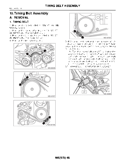
TIMING BELT ASSEMBLY MECHANICAL 15.Timing Belt Assembly A: REMOVAL 1. TIMING BELT 1) Remove the V-belt.2) Remove the crankshaft pulley. 3) Remove the timing belt cover. ME-00729 4) Remove the timing belt guides. 5) If the alignment mark and/or arrow mark (which indicates rotation direction) on timing belt fade away, put new marks before removing the timing belt as follows: (1) Turn the crankshaft using ST, and align the alignment marks on crankshaft sprocket, intake camshaft sprocket (LH), exhaust camshaft sprocket (LH), intake camshaft sprocket (RH) and exhaust camshaft sprocket (RH) with notch- es of timing belt cover and cylinder block. ST 499987500 CRANKSHAFT SOCKET ME-00065 ST ME-00069 ME-00727 ME-00728 ME(STi)-46 TIMING BELT ASSEMBLY MECHANICAL (2) Using white paint, put alignment and/or ar- 7) Remove the timing belt. row marks on the timing belts in relation to the CAUTION: sprockets. After the timing belt has been removed, never rotate the intake and exhaust, camshaft sprock- et. If the camshaft sprocket is rotated, the in- take and exhaust valve heads strike together and valve stems are bent. 2. BELT IDLER AND AUTOMATIC BELT TENSION ADJUSTER ASSEMBLY 1) Remove the belt idler (B) and (C). EN-00070 (C) (B) (A) ME-00074 2) Remove the belt idler No. 2. ME-00071 Z1: 54.5 tooth length Z2: 51 tooth length Z3: 28 tooth length Z1 Z2 Z3 Z3 ME-00075 3) Remove the automatic belt tension adjuster as- sembly. ME-00072 6) Remove the belt idler (A). (C) (B) ME-00076 (A) ME-00073 ME(STi)-47 TIMING BELT ASSEMBLY MECHANICAL B: INSTALLATION 2) Install the automatic belt tension adjuster as- sembly. 1. AUTOMATIC BELT TENSION ADJUST- ER ASSEMBLY AND BELT IDLER Tightening torque: 39 N
◦ Jabse Service Manual Search 2026 ◦ Jabse Pravopis ◦ onTap.bg ◦ Other service manual resources online : Fixya ◦ eServiceinfo