Service Manuals, User Guides, Schematic Diagrams or docs for : . Car Manuals Subaru Impreza 2001-2002.2004-2007 Approved Subaru Impreza 2004 WRX STi 02. ENGINE SECTION (STi) 04. MECHANICAL 20. Cylinder Block
<< Back | HomeMost service manuals and schematics are PDF files, so You will need Adobre Acrobat Reader to view : Acrobat Download Some of the files are DjVu format. Readers and resources available here : DjVu Resources
For the compressed files, most common are zip and rar. Please, extract files with Your favorite compression software ( WinZip, WinRAR ... ) before viewing. If a document has multiple parts, You should download all, before extracting.
Good luck. Repair on Your own risk. Make sure You know what You are doing.
Image preview - the first page of the document
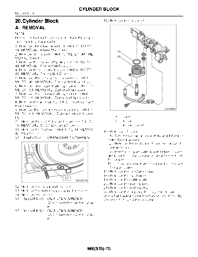
>> Download 20. Cylinder Block documenatation <<
Text preview - extract from the document
CYLINDER BLOCK MECHANICAL 20.Cylinder Block 15) Remove the oil cooler. A: REMOVAL NOTE: Before conducting this procedure, drain the engine oil completely if applicable. 1) Remove the intake manifold.(A) 2) Remove the V-belt. 3) Remove the crankshaft pulley. 4) Remove the timing belt cover. 5) Remove the timing belt assembly. 6) Remove the camshaft sprocket. 7) Remove the crankshaft sprocket. 8) Remove the generator and A/C compressor with their brackets. LU-00669 9) Remove the cylinder head assembly. (A) Gasket 10) Remove the clutch disc and cover. (C) Oil cooler connector 11) Remove the flywheel. (1) Turn the cylinder block with #2 and #4 piston ST 498497100 CRANKSHAFT STOPPER sides facing upward. (2) Remove the bolts which secure oil pan to cylinder block. (3) Insert an oil pan cutter blade between cylin- der block-to-oil pan clearance, and then remove the oil pan. Do not use a screwdriver or similar tool in place of oil pan cutter. 17) Remove the oil strainer stay. 18) Remove the oil strainer. ST ME-00778 19) Remove the baffle plate. 20) Remove the water pipes. 12) Remove the oil separator cover. 21) Remove the water pump. 13) Remove the water by-pass pipe for heater. 22) Remove the oil pump from cylinder block. 14) Remove the oil filter. Use a flat-bladed screwdriver as shown in the fig- ST 18332AA000 OIL FILTER WRENCH ure when removing the oil pump. (Outer diameter: 68 mm (2.68 in)) ST 18332AA010 OIL FILTER WRENCH (Outer diameter: 65 mm (2.56 in)) ME(STi)-70 CYLINDER BLOCK MECHANICAL NOTE: Be careful not to scratch the mating surface of cyl- inder block and oil pump. ME-00138 (1) (2) (3) (4) (6) (4) (5) (3) (4) (3) (2) (1) (4) (3) (2) (1) ME-00139 (1) Service hole plug (3) Circlip (5) Service hole cover (2) Gasket (4) Piston pin (6) O-ring ME(STi)-71 CYLINDER BLOCK MECHANICAL 23) Remove the service hole cover and service 29) Set up the cylinder block so that #1 and #3 cyl- hole plugs using hexagon wrench [14 mm (0.55 inders are on the upper side, then remove the cyl- in)]. inder block connecting bolts. 30) Separate the cylinder blocks (LH) and (RH). ME-00140 24) Rotate the crankshaft to bring #1 and #2 pis- tons to bottom dead center position, and then re- move the piston circlip through service hole of #1 and #2 cylinders. ME-00141 25) Draw out the piston pin from #1 and #2 pistons using ST. ST 499097600 PISTON PIN REMOVER NOTE: Be careful not to confuse the original combination of piston, piston pin and cylinder. ST ME-00142 26) Similarly remove the piston pins from #3 and #4 pistons. 27) Remove the bolts which connect the cylinder block on the side of #2 and #4 cylinders. 28) Back off the bolts which connect the cylinder block on the side of #1 and #3 cylinders two or three turns. ME(STi)-72 CYLINDER BLOCK MECHANICAL NOTE: When separating the cylinder block, do not allow the connecting rod to fall and damage the cylinder block. (5) (1) (4) (2) (4) (3) (1) (5) ME-00143 (1) Cylinder block (3) Crankshaft (5) Piston (2) Rear oil seal (4) Crankshaft bearing 31) Remove the rear oil seal. 32) Remove the crankshaft together with connect- ing rod. 33) Remove the crankshaft bearings from cylinder block using a hammer handle. NOTE: Do not confuse the combination of crankshaft bear- ings. Press the bearing at the end opposite to locking lip. 34) Draw out each piston from cylinder block using a wooden bar or hammer handle. NOTE: Do not confuse the combination of piston and cylin- der. ME(STi)-73 CYLINDER BLOCK MECHANICAL B: INSTALLATION (4) (1) (3) (2) (3) ME-00144 (1) Crankshaft bearing (3) Cylinder block (4) Rear oil seal (2) Crankshaft 1) Remove oil in the mating surface of bearing and 4) Apply engine oil to washers and thread of bolts. cylinder block before installation. Also apply a coat 5) Tighten the 10 mm cylinder block connecting of engine oil to crankshaft pins. bolts in alphabetical sequence shown in the figure. 2) Position the crankshaft on #2 and #4 cylinder (LH side) block. Tightening torque: 3) Apply fluid packing to the mating surface of #1 10 N
◦ Jabse Service Manual Search 2026 ◦ Jabse Pravopis ◦ onTap.bg ◦ Other service manual resources online : Fixya ◦ eServiceinfo