Service Manuals, User Guides, Schematic Diagrams or docs for : . Car Manuals Subaru Impreza 2001-2002.2004-2007 Approved Subaru Impreza 2004 WRX STi 04. TRANSMISSION 01. CONTROL SYSTEMS 05. AT Shift Lock Solenoid and
<< Back | HomeMost service manuals and schematics are PDF files, so You will need Adobre Acrobat Reader to view : Acrobat Download Some of the files are DjVu format. Readers and resources available here : DjVu Resources
For the compressed files, most common are zip and rar. Please, extract files with Your favorite compression software ( WinZip, WinRAR ... ) before viewing. If a document has multiple parts, You should download all, before extracting.
Good luck. Repair on Your own risk. Make sure You know what You are doing.
Image preview - the first page of the document
>> Download 05. AT Shift Lock Solenoid and documenatation <<
Text preview - extract from the document
                 AT SHIFT LOCK SOLENOID AND "P" RANGE SWITCH
                                                                                       CONTROL SYSTEMS

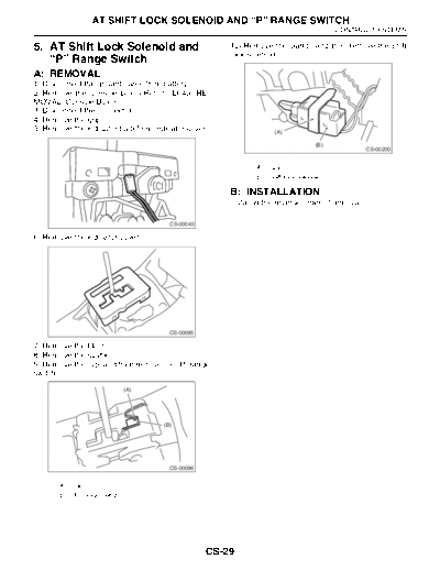
5. AT Shift Lock Solenoid and                        10) Remove the clamp, and then remove the shift
                                                     lock solenoid.
   "P" Range Switch
A: REMOVAL
1) Disconnect the ground cable from battery.
2) Remove the console box.
3) Disconnect the connector.
4) Remove the grip.
5) Remove the indicator bulb from indicator cover.                 (A)

                                                                                 (B)
                                                                                                CS-00200


                                                            (A) Clamp
                                                            (B) Shift lock solenoid

                                                     B: INSTALLATION
                                                     Install in the reverse order of removal.

                                      CS-00043

6) Remove the indicator cover.


                                      CS-00095

7) Remove the blind.
8) Remove the cushion.
9) Remove the clip, and then remove the "P" range
switch.

                             (A)


                                    (B)


                                      CS-00096


      (A) Clip
      (B) "P" range switch


                                                 CS-29
               AT SHIFT LOCK SOLENOID AND "P" RANGE SWITCH
CONTROL SYSTEMS

C: INSPECTION
                      Step                                         Check                     Yes               No
1     CHECK SHIFT LOCK SOLENOID.                      Is the resistance between 20    Go to step 2.    Replace the shift
      Measure the resistance of shift lock solenoid   and 40 ?                                         lock solenoid and
      connector terminals.                                                                             "P" range switch
        Terminals                                                                                      assembly.
         No. 4 -- No. 5:
2     CHECK SHIFT LOCK SOLENOID.                      Is the shift lock solenoid oper- Go to step 3.   Replace the shift
      Connect the battery with shift lock solenoid    ating properly?                                  lock solenoid and
      connector terminal, operate solenoid.                                                            "P" range switch
        Terminals                                                                                      assembly.
         No. 4 (+) -- No. 5 (-):
3     CHECK "P" RANGE SWITCH.                         Is the resistance less than 1   Go to step 4.    Replace the "P"
      1)Move the select lever to "P" range.           ?                                                range switch.
      2)Measure the resistance between "P" range
      switch connector terminals.
4     CHECK "P" RANGE SWITCH.                         Is the resistance more than 1   Normal           Replace the "P"
      1)Move the select lever to other than "P"       M?                                               range switch.
      range.
      2)Measure the resistance between "P" range
      switch connector terminals.


                                                       CS-30
◦ Jabse Service Manual Search 2026 ◦ Jabse Pravopis ◦ onTap.bg ◦ Other service manual resources online : Fixya ◦ eServiceinfo