Service Manuals, User Guides, Schematic Diagrams or docs for : . Car Manuals Subaru Impreza 2001-2002.2004-2007 Approved Subaru Impreza 2004 WRX STi 05. CHASSIS 01. FRONT SUSPENSION 03. Front Transverse Link
<< Back | HomeMost service manuals and schematics are PDF files, so You will need Adobre Acrobat Reader to view : Acrobat Download Some of the files are DjVu format. Readers and resources available here : DjVu Resources
For the compressed files, most common are zip and rar. Please, extract files with Your favorite compression software ( WinZip, WinRAR ... ) before viewing. If a document has multiple parts, You should download all, before extracting.
Good luck. Repair on Your own risk. Make sure You know what You are doing.
Image preview - the first page of the document
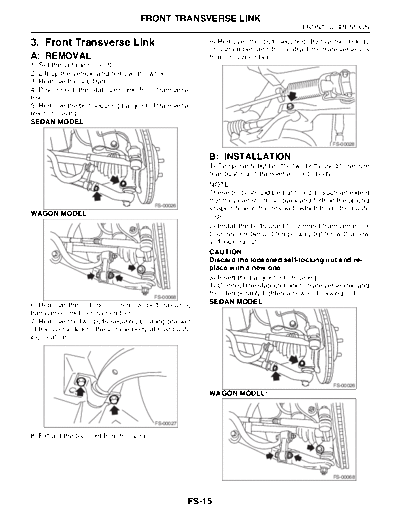
>> Download 03. Front Transverse Link documenatation <<
Text preview - extract from the document
                                    FRONT TRANSVERSE LINK
                                                                                        FRONT SUSPENSION

3. Front Transverse Link                                 9) Remove the bolt securing transverse link to
                                                         crossmember, and then extract the transverse link
A: REMOVAL                                               from crossmember.
1) Set the vehicle on a lift.
2) Lift-up the vehicle and remove the wheel.
3) Remove the sub frame.
4) Disconnect the stabilizer link from transverse
link.
5) Remove the bolt securing ball joint of transverse
link to housing.
SEDAN MODEL:


                                                                                                  FS-00028

                                                         B: INSTALLATION
                                                         1) Temporarily tighten the two bolts used to secure
                                                         rear bushing of transverse link to body.
                                                         NOTE:
                                                         These bolts should be tightened to such an extent
                                                         that they can still move back and forth in the oblong
                                          FS-00026
                                                         shaped hole in the bracket (which holds the bush-
WAGON MODEL:                                             ing).
                                                         2) Install the bolts used to connect transverse link
                                                         to crossmember and temporarily tighten with a new
                                                         self-locking nut.
                                                         CAUTION:
                                                         Discard the loosened self-locking nut and re-
                                                         place with a new one.
                                                         3) Insert the ball joint into housing.
                                                         4) Connect the stabilizer link to transverse link, and
                                          FS-00068
                                                         then temporarily tighten a new self-locking nut.
6) Remove the nut (do not remove bolt) securing          SEDAN MODEL:
transverse link to crossmember.
7) Remove the two bolts securing bushing bracket
of transverse link to the vehicle body at rear bush-
ing location.


                                                                                                  FS-00026
                                                         WAGON MODEL:


                                          FS-00027

8) Extract the ball joint from housing.


                                                                                                  FS-00068


                                                     FS-15
                                    FRONT TRANSVERSE LINK
FRONT SUSPENSION

5) Tighten the following points in the order shown      C: DISASSEMBLY
below when tires are in full contact with the ground
and vehicle is curb weight.                             1. FRONT BUSHING
   (1) Transverse link and stabilizer                   Using the ST, press the front bushing out of place.
Tightening torque:                                      ST 927680000        INSTALLER & REMOVER
  STi model:                                                                SET
     45 N
◦ Jabse Service Manual Search 2026 ◦ Jabse Pravopis ◦ onTap.bg ◦ Other service manual resources online : Fixya ◦ eServiceinfo