Service Manuals, User Guides, Schematic Diagrams or docs for : . Car Manuals Subaru Impreza 2001-2002.2004-2007 Approved Subaru Impreza 2004 WRX STi 05. CHASSIS 06. DRIVE SHAFT SYSTEM 04. Rear Axle
<< Back | HomeMost service manuals and schematics are PDF files, so You will need Adobre Acrobat Reader to view : Acrobat Download Some of the files are DjVu format. Readers and resources available here : DjVu Resources
For the compressed files, most common are zip and rar. Please, extract files with Your favorite compression software ( WinZip, WinRAR ... ) before viewing. If a document has multiple parts, You should download all, before extracting.
Good luck. Repair on Your own risk. Make sure You know what You are doing.
Image preview - the first page of the document
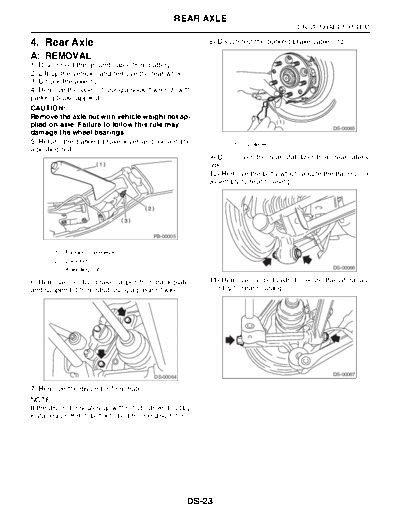
>> Download 04. Rear Axle documenatation <<
Text preview - extract from the document
                                                 REAR AXLE
                                                                                       DRIVE SHAFT SYSTEM

4. Rear Axle                                              8) Disconnect the parking brake cable end.

A: REMOVAL
1) Disconnect the ground cable from battery.
2) Lift-up the vehicle, and remove the rear wheel.
3) Unlock the axle nut.
4) Remove the axle nut using a socket wrench with
parking brake applied.
CAUTION:
Remove the axle nut with vehicle weight not ap-
                                                                                 (1)
plied on axle. Failure to follow this rule may                                                   DS-00065
damage the wheel bearings.
5) Return the parking brake lever and loosen the                 (1) Cable end
adjusting nut.
                                                          9) Disconnect the rear stabilizer from rear lateral
                                                          link.
                                                          10) Remove the bolts which secure the trailing link
                                                          assembly to rear housing.


                                          PB-00005


       (1) Parking brake lever
       (2) Lock nut
       (3) Adjusting nut                                                                         DS-00066


6) Remove the disc brake caliper from back plate,         11) Remove the bolts which secure the lateral as-
and suspend it from strut using a piece of wire.          sembly to rear housing.


                                                                                                 DS-00067
                                          DS-00064

7) Remove the disc rotor from hub.
NOTE:
If the disc rotor seizes up within hub, drive it out by
installing an 8-mm bolt into bolt hole in disc rotor.


                                                     DS-23
                                                 REAR AXLE
DRIVE SHAFT SYSTEM

12) Remove the rear ABS wheel speed sensor               B: INSTALLATION
from back plate.                                         1) Temporarily tighten the rear axle to strut.
                                                         2) Insert the rear drive shaft into rear axle.
                                                         NOTE:
                                                         Be careful not to damage the inner oil seal lip.
                                                         3) Temporarily tighten the axle nut.
                                                         4) Using a new self-locking nut, temporarily tighten
                                                         the rear housing assembly and lateral link assem-
                                                         bly.
                                          (1)


                                          DS-00069


       (1) ABS wheel speed sensor

13) Disengage the BJ from housing splines, and
then remove the rear drive shaft assembly.
If it is hard to remove, use the STs.
ST1 926470000 AXLE SHAFT PULLER
ST2 927140000 AXLE SHAFT PULLER                                                                   DS-00067
                      PLATE
                                                         5) Using a new self-locking nut, temporarily tighten
NOTE:                                                    the rear housing assembly and trailing link assem-
◦ Jabse Service Manual Search 2026 ◦ Jabse Pravopis ◦ onTap.bg ◦ Other service manual resources online : Fixya ◦ eServiceinfo