Service Manuals, User Guides, Schematic Diagrams or docs for : . Car Manuals Subaru Impreza 2001-2002.2004-2007 Approved Subaru Impreza 2004 WRX STi 05. CHASSIS 09. BRAKE 14. Brake Pedal
<< Back | HomeMost service manuals and schematics are PDF files, so You will need Adobre Acrobat Reader to view : Acrobat Download Some of the files are DjVu format. Readers and resources available here : DjVu Resources
For the compressed files, most common are zip and rar. Please, extract files with Your favorite compression software ( WinZip, WinRAR ... ) before viewing. If a document has multiple parts, You should download all, before extracting.
Good luck. Repair on Your own risk. Make sure You know what You are doing.
Image preview - the first page of the document
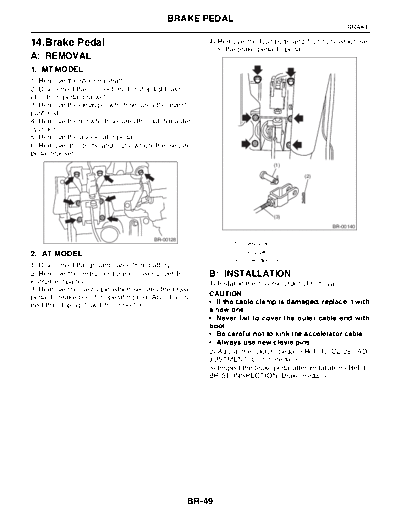
>> Download 14. Brake Pedal documenatation <<
Text preview - extract from the document
                                            BRAKE PEDAL
                                                                                                     BRAKE

14.Brake Pedal                                         4) Remove the four bolts and four nuts which se-
                                                       cure the brake pedal to pedal.
A: REMOVAL
1. MT MODEL
1) Remove the steering shaft.
2) Disconnect the connectors (for stop light switch,
etc.) from pedal bracket.
3) Remove the clevis pin which secures the lever to
push rod.
4) Remove the nut which secures the clutch master
cylinder.
5) Remove the accelerator pedal.
6) Remove the bolts and nuts which the secure
pedal bracket.
                                                                            (1)

                                                                                       (2)


                                                                            (3)
                                                                                                BR-00140

                                        BR-00128
                                                              (1) Clevis pin
2. AT MODEL                                                   (2) Snap pin
                                                              (3) Operating rod
1) Disconnect the ground cable from battery.
2) Remove the instrument panel lower cover from        B: INSTALLATION
instrument panel.                                      1) Install in the reverse order of removal.
3) Remove the clevis pin which secures the brake
pedal to brake booster operating rod. Also discon-     CAUTION:
nect the stop light switch connector.
◦ Jabse Service Manual Search 2026 ◦ Jabse Pravopis ◦ onTap.bg ◦ Other service manual resources online : Fixya ◦ eServiceinfo