Service Manuals, User Guides, Schematic Diagrams or docs for : . Car Manuals Subaru Impreza 2001-2002.2004-2007 Approved Subaru Impreza 2004 WRX STi 06. BODY 02. HVAC SYSTEM (AUTO AC) (DIAGNOSTICS) 04. AC Control Module IO Signal
<< Back | HomeMost service manuals and schematics are PDF files, so You will need Adobre Acrobat Reader to view : Acrobat Download Some of the files are DjVu format. Readers and resources available here : DjVu Resources
For the compressed files, most common are zip and rar. Please, extract files with Your favorite compression software ( WinZip, WinRAR ... ) before viewing. If a document has multiple parts, You should download all, before extracting.
Good luck. Repair on Your own risk. Make sure You know what You are doing.
Image preview - the first page of the document
>> Download 04. AC Control Module IO Signal documenatation <<
Text preview - extract from the document
                                           A/C CONTROL MODULE I/O SIGNAL
                                                                                            HVAC SYSTEM (AUTO A/C) (DIAGNOSTICS)

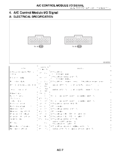
4. A/C Control Module I/O Signal
A: ELECTRICAL SPECIFICATION


                              8   7    6   5    4   3   2   1                        10 9    8   7   6   5   4   3   2   1
                              16 15 14 13 12 11 10 9                                 20 19 18 17 16 15 14 13 12 11


                                      To A: B282                                             To B: B283


                                                                                                                                    AC-00735


                                               Connector &
             Content                                                                                 Signal (V)
                                               Terminal No.
Battery power supply (Memory                                    Battery voltage,
                                                B1 -- B12
back-up)                                                        13 -- 14 (engine running)
                                                                Battery voltage (ignition switch ON),
IGN power supply                                A8 -- B12
                                                                13 -- 14 (engine running)
ACC power supply                                B2 -- B12       Battery voltage, 0 (engine cranking), Battery voltage (engine running)
                                               B12 -- chas-
A/C control module ground circuit                               0 (ignition switch ON) -- circuit constantly grounded to chassis
                                                sis ground
                                               B17 -- chas-
Sensor ground circuit                                           0 (ignition switch ON) -- circuit constantly grounded to chassis
                                                sis ground
Ambient sensor                                  B9 -- B17
Evaporator sensor                               B7 -- B17       Approx. 5 (disconnect connector, and ignition switch ON)
Thermometer                                    B15 -- B12
Sunload sensor                                 B16 -- B17       Approx. 5 (disconnect connector, and ignition switch ON)
Air mix door actuator                            B5 -- B1       Battery voltage (ignition switch ON)
Air mix door actuator P.B.R.                    A4 -- B17       LAN connection
Mode door actuator                              B6 -- B17       Battery voltage (ignition switch ON)
Mode door actuator P.B.R.                      A12 -- B17       LAN connection
Intake door FRS voltage                         A15 -- A7       Battery voltage (FRESH/RECIRC switch OFF)
Intake door CIRC voltage                        A7 -- A15       Battery voltage (FRESH/RECIRC switch ON)
Blower fan relay                               B14 -- body      Battery voltage (ignition switch ON)
                                                                0 (ignition and A/C switches ON)
A/C relay                                       B3 -- B12
                                                                Battery voltage (A/C switch OFF)
Illumination control signal                    B10 -- B20       Battery voltage (ignition and lighting switches ON)
Rear window defogger                           A13 -- B12       0 (ignition switch ON, rear window defogger switch ON)


                                                                        AC-7
                         A/C CONTROL MODULE I/O SIGNAL
HVAC SYSTEM (AUTO A/C) (DIAGNOSTICS)

B: SCHEMATIC
1. AIR CONDITIONER AUTO A/C MODEL


                                           AC-8
◦ Jabse Service Manual Search 2026 ◦ Jabse Pravopis ◦ onTap.bg ◦ Other service manual resources online : Fixya ◦ eServiceinfo