Service Manuals, User Guides, Schematic Diagrams or docs for : . Car Manuals Subaru Impreza 2001-2002.2004-2007 Approved Subaru Impreza 2004 WRX STi 06. BODY 14. SECURITY AND LOCKS 04. Security System
<< Back | HomeMost service manuals and schematics are PDF files, so You will need Adobre Acrobat Reader to view : Acrobat Download Some of the files are DjVu format. Readers and resources available here : DjVu Resources
For the compressed files, most common are zip and rar. Please, extract files with Your favorite compression software ( WinZip, WinRAR ... ) before viewing. If a document has multiple parts, You should download all, before extracting.
Good luck. Repair on Your own risk. Make sure You know what You are doing.
Image preview - the first page of the document
>> Download 04. Security System documenatation <<
Text preview - extract from the document
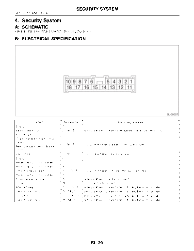
SECURITY SYSTEM SECURITY AND LOCKS 4. Security System A: SCHEMATICB: ELECTRICAL SPECIFICATION 10 9 8 7 6 5 4 3 2 1 18 17 16 15 14 13 12 11 SL-00037 Content Terminal No. Measuring condition Empty 1 -- Ignition switch (ON) 2 (INPUT) Battery voltage is present when ignition switch is turned to ON. Passive arm 3 -- Trunk room light switch (Sedan model) 4 (INPUT) 0 V is present when trunk lid or rear gate is open. Rear gate latch switch (Wagon model) Door switch 5 (INPUT) 0 V is present when any door is open. Empty 6 -- Keyless entry control module 7 -- Keyless entry control module 8 -- Security indicator light 9 (OUTPUT) 0 V is present when activating the alarm operation. Keyless entry control module 10 -- Power supply (Back-up) 13 Battery voltage is constantly present. Ground 14 0 V is constantly present. Interrupt relay 15 (OUTPUT) Battery voltage is present when activating the alarm operation. Security horn relay 16 (INPUT) Battery voltage is present when activating the alarm operation. Security horn 17 (OUTPUT) Battery voltage is present when activating the alarm operation. Security horn relay 18 (INPUT) Battery voltage is present when activating the alarm operation. SL-20 SECURITY SYSTEM SECURITY AND LOCKS C: INSPECTION 1. BASIC DIAGNOSTIC PROCEDURE Step Check Yes No 1 CHECK VALET MODE SETTING. Does the security indicator Go to step 2. Go to step 3. Check the valet mode is set. (Security indicator light blink two times per a sec- light blinks two times per a second when the ond? valet mode is set.) 2 RELEASE VALET MODE SETTING. Does the security indicator Go to step 3. Go to symptom 1. Release the valet mode setting. light blink one time per two 3 CHECK SECURITY SYSTEM SET OPERA- Can the security system be Go to step 4. Go to symptom 1. TION. set? 3)Press the LOCK/ARM button of transmitter. 4 CHECK SECURITY INDICATOR LIGHT AND Do the security indicator light Go to step 5. Go to symptom 2. HAZARD LIGHT BLINKING. and hazard light blink? 5 CHECK SECURITY ALARM OPERATION. Does the security alarm oper- Go to step 6. Go to symptom 3. 1)Unlock all doors using the door lock switch ate when any door, trunk lid or 6 CHECK SECURITY ALARM OPERATION. Does all security alarm (horn, Go to step 7. Go to symptom 4. Check the security alarm operation. hazard light and security indi- 7 CHECK SECURITY ALARM CANCEL OPER- Do all security alarm (horn and Go to step 8. Go to symptom 5. ATION. hazard light) stop? And is the 8 CHECK BATTERY DISCONNECT PROTEC- Is the battery disconnect pro- Go to step 9. Replace the secu- TION. tection OK? rity control mod- Check the battery disconnect protection. 9 PERFORM IMPACT SENSITIVITY TEST. Is the impact sensitivity prop- Press the Adjust the impact Perform the impact sensitivity test. transmitter, and SENSITIVITY, finish the diagno- ADJUSTMENT, sis. Security Control Module.> SL-21 SECURITY SYSTEM SECURITY AND LOCKS 2. CHECK BATTERY DISCONNECT PROTECTION 1) Remove the key from the ignition switch. 2) Close all the doors, trunk lid and rear gate. 3) Open the front hood. 4) Press the LOCK/ARM button of the transmitter. 5) Disconnect the ground cable from the battery. 6) Reconnect the cable to the battery. 7) Check that the security indicator light blinks after reconnecting the battery cable. If NG, replace the security control module. 3. SYMPTOM CHART Symptom Repair order Reference 1 Security system cannot be set. 1. Check the transmitter func- 2. Check the fuse. 3. Check the security control 4. Check the door switch. 5. Replace the security control 2 Security indicator light or haz- Security indica- Check the security indicator light Hazard light Check the hazard light opera- 3 Security system does not alarm when one of the Check the door switch. 4 Security alarm does not acti- All functions Check the door switch. Security indica- Check the security indicator light Security horn Check the security horn. Hazard light Check the hazard light opera- Starter motor Check the interrupt relay circuit. 5 Security system cannot be can- Transmitter Check the transmitter function. Ignition switch Check the ignition switch circuit. SL-22 SECURITY SYSTEM SECURITY AND LOCKS 4. CHECK FUSE Step Check Yes No 1 CHECK FUSE. Is the fuse blown out? Check the power Replace the fuse Remove and visually check the fuse No. 2 (in supply and ground with a new one. main fuse box). circuit. 5. CHECK POWER SUPPLY AND GROUND CIRCUIT Step Check Yes No 1 CHECK POWER SUPPLY. Is the voltage more than 10 V? Go to step 2. Check the harness 1)Disconnect the security control module har- for open circuits ness connector. and shorts 2)Measure the voltage between the harness between the secu- connector terminal and chassis ground. rity control module Connector & terminal and fuse. (B93) No. 13 (+) -- Chassis ground (-): 2 CHECK GROUND CIRCUIT. Is the resistance less than 10 The power supply Repair the har- Measure the resistance between the harness ? and ground circuit ness. connector terminal and chassis ground. are OK. Connector & terminal (B93) No. 14 -- Chassis ground: 6. CHECK DOOR SWITCH Step Check Yes No 1 CHECK DOOR SWITCH CIRCUIT. Is the voltage 0 V? Go to step 2. Go to step 3. Measure the voltage between the security con- trol module harness connector terminal and chassis ground when any door or rear gate is opened. Connector & terminal Front and rear door: (B93) No. 5 (+) -- Chassis ground (-): Trunk lid or rear gate: (B93) No. 4 (+) -- Chassis ground (-): 2 CHECK DOOR SWITCH CIRCUIT. Is the voltage more than 10 V? The door switch is Go to step 3. Measure the voltage between the security con- OK. trol module harness connector terminal and chassis ground when all doors and rear gate are closed. Connector & terminal Front and rear door: (B93) No. 5 (+) -- Chassis ground (-): Trunk lid or rear gate: (B93) No. 4 (+) -- Chassis ground (-): SL-23 SECURITY SYSTEM SECURITY AND LOCKS Step Check Yes No 3 CHECK DOOR SWITCH. Is the resistance more than 1 Go to step 4. Replace the door 1)Disconnect the door switch harness connec- M when door switch is switch. tor. pushed? 2)Measure the resistance between the door switch terminals. Terminals Door switch No. 1 -- No. 3: Rear gate latch switch (Wagon model) No. 1 -- No. 2: Trunk room light switch (Sedan model) No. 1 -- No. 2: 4 CHECK DOOR SWITCH. Is the resistance less than 1 Check the harness Replace the door Measure the resistance between the door when door switch is released? for open circuits switch. switch terminals. and shorts Terminals between the secu- Door switch No. 1 -- No. 3: rity control module Rear gate latch switch (Wagon model) and door switch. No. 1 -- No. 2: Trunk room light switch (Sedan model) No. 1 -- No. 2: 7. CHECK SECURITY INDICATOR LIGHT CIRCUIT Step Check Yes No 1 CHECK SECURITY INDICATOR LIGHT. Does the security indicator Replace the secu- Go to step 2. 1)Disconnect the security control module har- light illuminate? rity control mod- ness connector. ule. 2)Ground the harness connector terminal with a suitable wire. Connector & terminal (B93) No. 9 -- Chassis ground: 2 CHECK POWER SUPPLY FOR SECURITY Is the voltage more than 10 V? Go to step 3. Check the harness INDICATOR LIGHT. for open circuits 1)Disconnect the connector from the combina- and shorts tion meter. between the com- 2)Measure the voltage between the combina- bination meter and tion meter harness connector terminal and the fuse. chassis ground. Connector & terminal (i11) No. 3 (+) -- Chassis ground (-): 3 CHECK SECURITY INDICATOR LIGHT CIR- Is the resistance less than 10 Replace the com- Check the harness CUIT. ? bination meter for open circuits Measure the resistance between the combina- printed circuit. and shorts tion meter harness connector terminal and between the com- security control module harness connector ter- bination meter and minal. security control Connector & terminal module. (i10) No. 6 -- (B93) No. 9: SL-24 SECURITY SYSTEM SECURITY AND LOCKS 8. CHECK SECURITY HORN Step Check Yes No 1 CHECK SECURITY HORN RELAY. Is the security horn relay OK? Go to step 2. Replace the secu- Remove and check the security horn relay. rity horn relay. 2 CHECK POWER SUPPLY FOR SECURITY Is the voltage more than 10 V? Go to step 3. Check the harness HORN RELAY. for open circuits Measure the voltage between the security horn and shorts relay harness connector terminal and chassis between the secu- ground. rity horn relay and Connector & terminal horn relay. (B243) No. 1 (+) -- Chassis ground (-): 3 CHECK POWER SUPPLY FOR SECURITY Is the voltage more than 10 V? Go to step 4. Check the harness HORN RELAY. for open circuits Measure the voltage between the security horn and shorts relay harness connector terminal and chassis between the secu- ground. rity horn relay and Connector & terminal the fuse. (B243) No. 2 (+) -- Chassis ground (-): 4 CHECK HARNESS BETWEEN SECURITY Is the resistance less than 10 Go to step 5. Check the harness HORN RELAY AND SECURITY CONTROL ? for open circuits MODULE. and shorts 1)Disconnect the security control module har- between the secu- ness connector. rity horn relay and 2)Measure the resistance between the security security control horn relay harness connector terminal and module. security control module harness connector ter- minal. Connector & terminal (B243) No. 3 -- (B93) No. 18: 5 CHECK HARNESS BETWEEN SECURITY Is the resistance less than 10 Go to step 6. Check the harness HORN RELAY AND SECURITY CONTROL ? for open circuits MODULE. and shorts Measure the resistance between the security between the secu- horn relay harness connector terminal and rity horn relay and security control module harness connector ter- security control minal. module. Connector & terminal (B243) No. 4 -- (B93) No. 16: 6 CHECK HARNESS BETWEEN SECURITY Is the resistance less than 10 Go to step 7. Check the harness CONTROL MODULE AND SECURITY HORN. ? for open circuits 1)Disconnect the security horn harness con- and shorts nector. between the secu- 2)Measure the resistance between the security rity control module control module harness connector terminal and security horn. and security horn harness connector terminal. Connector & terminal (B93) No. 17 -- (B204) No. 1: 7 CHECK SECURITY HORN. Is the security horn OK? Replace the secu- Replace the secu- Remove and check the security horn. ule. SL-25 SECURITY SYSTEM SECURITY AND LOCKS 9. CHECK HAZARD LIGHT OPERATION Step Check Yes No 1 CHECK SECURITY CONTROL MODULE Is the voltage 1 -- 4 V? Go to step 2. Replace the secu- OUTPUT SIGNAL. rity control mod- 1)Remove the key from the ignition switch. ule. 2)Open the driver's window, and then close all doors and rear gate. 3)Lock all doors with the transmitter or door lock switch to arm the security system. 4)Unlock all doors with the door lock switch. 5)Measure the voltage between the security control module harness connector terminal and chassis ground when any door is open. Connector & terminal (B93) No. 10 -- Chassis ground: 2 CHECK HARNESS BETWEEN SECURITY Is the resistance less than 10 Check the hazard Check the harness CONTROL MODULE AND KEYLESS ENTRY ? light output of key- for open circuit CONTROL MODULE. less entry control and shorts 1)Disconnect the security control module har- module. Connector & terminal (B93) No. 10 -- (B176) No. 3: SL-26 SECURITY SYSTEM SECURITY AND LOCKS 10.CHECK INTERRUPT RELAY CIRCUIT Step Check Yes No 1 CHECK INTERRUPT RELAY. Is the interrupt relay OK? Go to step 2. Replace the inter- Remove and check the interrupt relay. 2 CHECK POWER SUPPLY FOR INTERRUPT Is the voltage more than 10 V Go to step 3. Check the harness RELAY. when ignition switch is turned for open circuits Measure the voltage between the interrupt to START? and shorts relay harness connector terminal and chassis between the inter- ground. rupt relay and igni- Connector & terminal tion switch. (B59) No. 1 (+) -- Chassis ground (-): 3 CHECK HARNESS BETWEEN INTERRUPT Is the resistance less than 10 Replace the secu- Check the harness RELAY AND SECURITY CONTROL MOD- ? rity control mod- for open circuits ULE. ule. and shorts 1)Turn the ignition switch to OFF. between the inter- 2)Disconnect the security control module har- rupt relay and ness connector. security control 3)Measure the resistance between the inter- module. rupt relay harness connector terminal and security control module harness connector ter- minal. Connector & terminal (B59) No. 4 -- (B93) No. 15: 11.CHECK IGNITION SWITCH CIRCUIT Step Check Yes No 1 CHECK IGNITION SWITCH SIGNAL. Is the voltage more than 10 V? Ignition switch cir- Check the harness 1)Disconnect the security control module har- cuit is OK. for open circuits ness connector. and shorts 2)Turn the ignition switch to ON. between the secu- 3)Measure the voltage between the harness rity control module connector terminal and chassis ground. and ignition Connector & terminal switch. (B93) No. 2 (+) -- Chassis ground (-): SL-27
◦ Jabse Service Manual Search 2026 ◦ Jabse Pravopis ◦ onTap.bg ◦ Other service manual resources online : Fixya ◦ eServiceinfo