Service Manuals, User Guides, Schematic Diagrams or docs for : . Car Manuals Subaru Impreza 2001-2002.2004-2007 Approved Subaru Impreza 2004 WRX STi 08. MECHANISM AND FUNCTION 22. FUEL INJECTION (FUEL SYSTEM STi) 02. Air Line
<< Back | HomeMost service manuals and schematics are PDF files, so You will need Adobre Acrobat Reader to view : Acrobat Download Some of the files are DjVu format. Readers and resources available here : DjVu Resources
For the compressed files, most common are zip and rar. Please, extract files with Your favorite compression software ( WinZip, WinRAR ... ) before viewing. If a document has multiple parts, You should download all, before extracting.
Good luck. Repair on Your own risk. Make sure You know what You are doing.
Image preview - the first page of the document
>> Download 02. Air Line documenatation <<
Text preview - extract from the document
W1860BE.book Page 3 Tuesday, January 28, 2003 11:01 PM


                                                               AIR LINE
                                                                                          FUEL INJECTION (FUEL SYSTEM)


           2. Air Line
           A: GENERAL
           The air filtered by the air cleaner enters the throttle body where it is regulated in the volume by the
           throttle valve and then enters the intake manifold. It is then distributed to each cylinder where the
           air is mixed with fuel injected by the injector.
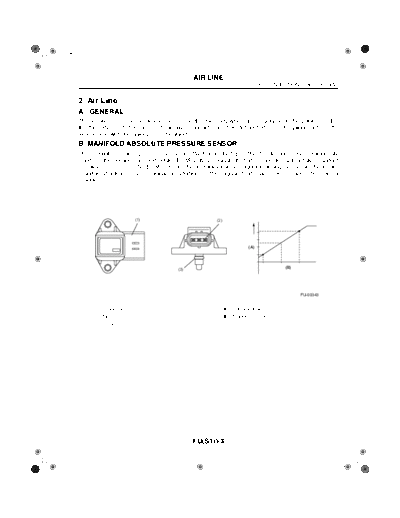
           B: MANIFOLD ABSOLUTE PRESSURE SENSOR
           The manifold absolute pressure sensor is attached to the top of the throttle body, and continuously
           sends to the engine control module (ECM) voltage signals that are proportional to intake manifold
           absolute pressures. The ECM controls the fuel injection and ignition timing based on the intake
           manifold absolute pressure signals in addition to other signals from many sensors and other control
           modules.


                                              (1)                     (2)


                                                                                    (A)


                                                         (3)                                       (B)


                                                                                                         FU-00343


                    (1) Connector                                       (A) Output voltage
                    (2) Terminal                                        (B) Absolute pressure
                    (3) O-ring


                                                               FU(STi)-3
W1860BE.book Page 4 Tuesday, January 28, 2003 11:01 PM


                                                         AIR LINE
 FUEL INJECTION (FUEL SYSTEM)


 C: ELECTRONIC CONTROL THROTTLE SYSTEM
   The electronic control throttle system consists of an accelerator pedal position sensor mounted
 on the accelerator pedal, a throttle position sensor and a throttle motor mounted on the throttle body,
 and the ECM which controls these components.
    The movement of the accelerator pedal is converted into electrical signals by the accelerator ped-
 al position sensor and sent to the ECM.
     Based on these signals the ECM controls the throttle motor to open and close the throttle valve.

                                                                                                         (3)
                                                   (4)   (5)

                              (3)
           (1)


                    (2)


                                                                                                         (1)


                                                                                                         FU-01069


          (1) Throttle position sensor                           (4) Electronic control throttle relay
          (2) Accelerator pedal position sensor                  (5) ECM
          (3) Electronic control throttle assembly


                                                         FU(STi)-4
W1860BE.book Page 5 Tuesday, January 28, 2003 11:01 PM


                                                                     AIR LINE
                                                                                           FUEL INJECTION (FUEL SYSTEM)


           D: MASS AIR FLOW AND INTAKE AIR TEMPERATURE SENSOR
           The mass air flow and the intake air temperature sensors are integrated into a single unit. The unit
           is mounted on the air cleaner case and measures the amount as well as the temperature of the in-
           take air.
           The measured amount and temperature are converted into electrical signals and sent to the ECM.
           The ECM uses these signals to control injection and ignition timing as well as the fuel injection
           amount.


                                (1)

                                                                           (2)


                                                                                                            (3)
                                                                          (A)

                                                                                                             FU-00346


                    (1) Mass air flow and intake air temperature sensor          (A) Air
                    (2) Mass air flow sensor
                    (3) Intake air temperature sensor


           E: TUMBLE GENERATOR VALVE
             A tumble generator valve is provided on each engine bank, between the intake manifold and in-
           take air ports. The right bank tumble generator valve has butterfly valves for the #1 and #3 cylinders
           and the left bank tumble generator valve has those for the #2 and #4 cylinders. The two butterfly
           valves in each tumble generator valve are fitted on a single shaft that is driven by an actuator.
              The tumble generator valves are controlled by the ECM according to the coolant temperature and
           the time elapsed after start of the engine. When the engine is started, the butterfly valves are moved
           to the closing ends. In this state, the intake air flows at very high speeds passing through narrowed
           passages in the directions determined by the individual intake air ports in the cylinder head. This
           creates tumbling air motions in the cylinders, which enables lean mixtures to be ignited and thus
           harmful exhaust emissions to be reduced during engine start. The tumble generator valves are fully
           open when the engine is operating at an ordinary driving speed, allowing intake air to flow without
           being changed in direction and velocity.


                                                                     FU(STi)-5
W1860BE.book Page 6 Tuesday, January 28, 2003 11:01 PM


                                                                AIR LINE
 FUEL INJECTION (FUEL SYSTEM)


                                                                      (3)
                                                                                                             (1)
                        (2)


                                          (A)            (4)                (B)             (4)

                                           (5)            (6)                (5)             (6)

                                              (3)                             (3)
                                                                (9)                                (9)
                                                 (7)                             (7)


                                        (8)                            (8)
                                                         (10)                               (10)


                                                                                                         FU-00998


         (A) Activated
         (B) Not activated
          (1) Actuator                                                       (6) Tumble generating air passage
          (2) Tumble generator valve position sensor                         (7) Intake main air passage
          (3) Tumble generator housing                                       (8) Piston
          (4) Intake manifold                                                (9) Injector
          (5) Tumble generator valve                                        (10) Cylinder Head


                                                                FU(STi)-6
◦ Jabse Service Manual Search 2026 ◦ Jabse Pravopis ◦ onTap.bg ◦ Other service manual resources online : Fixya ◦ eServiceinfo