Service Manuals, User Guides, Schematic Diagrams or docs for : . Car Manuals Subaru Impreza 2001-2002.2004-2007 Approved Subaru Impreza 2004 WRX STi 08. MECHANISM AND FUNCTION 22. FUEL INJECTION (FUEL SYSTEM STi) 03. Fuel System
<< Back | HomeMost service manuals and schematics are PDF files, so You will need Adobre Acrobat Reader to view : Acrobat Download Some of the files are DjVu format. Readers and resources available here : DjVu Resources
For the compressed files, most common are zip and rar. Please, extract files with Your favorite compression software ( WinZip, WinRAR ... ) before viewing. If a document has multiple parts, You should download all, before extracting.
Good luck. Repair on Your own risk. Make sure You know what You are doing.
Image preview - the first page of the document
>> Download 03. Fuel System documenatation <<
Text preview - extract from the document
W1860BE.book Page 7 Tuesday, January 28, 2003 11:01 PM
FUEL SYSTEM
FUEL INJECTION (FUEL SYSTEM)
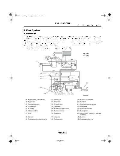
3. Fuel System
A: GENERAL
The fuel pressurized by the fuel tank inside pump is delivered to each fuel injector by way of the
fuel pipe and fuel filter. Fuel injection pressure is regulated to an optimum level by the pressure reg-
ulator.
Each injector injects fuel into the intake port of the corresponding cylinder where the fuel is mixed
with air. The mixture then enters the cylinder.
Fuel injection amount and timing are regulated by the ECM.
: (A)
: (B)
(3)
(1) (4)
(2) (24) (5)
(6)
(23) (25)
(22)
(7)
(21)
(13) (8)
(12) (9)
(20)
(19) (18) (17)(16) (15) (14) (11) (10)
FU-00790
(1) Purge control solenoid valve (10) Drain valve (19) Fuel sub level sensor
(2) Purge valve (11) Drain filter (20) Fuel tank
(3) Pressure regulator (12) Shut-off valve (21) Fuel tank pressure sensor
(4) Throttle body (13) Vent valve (22) Fuel gauge
(5) Fuel filter (14) Fuel temperature sensor (23) Combination meter
(6) Intake manifold (15) Fuel level sensor (24) Fuel injector
(7) ECM (16) Fuel pump (25) Atmospheric pressure switching
solenoid
(8) Canister (17) Jet pump (A) Fuel line
(9) Pressure control solenoid valve (18) Fuel cut valve (B) Fuel evaporation line
FU(STi)-7
W1860BE.book Page 8 Tuesday, January 28, 2003 11:01 PM
FUEL SYSTEM
FUEL INJECTION (FUEL SYSTEM)
B: PRESSURE REGULATOR
The pressure regulator is installed at the injector end of the fuel supply line. It has a fuel chamber
and spring chamber separated by a diaphragm. The fuel chamber is connected to the fuel supply
line and the spring chamber is connected to the intake manifold. Fuel chamber also has a relief
valve connected to the fuel return line through which fuel returns to the fuel tank. When the intake
manifold vacuum increases, the diaphragm is pulled and the relief valve opens to decrease the fuel
supply line pressure (or fuel injection pressure). When the intake manifold vacuum decreases, the
diaphragm is pushed by the spring to increase the fuel supply line pressure. Thus, the difference
between the fuel injection pressure and the intake manifold vacuum is kept at a constant level of
294 kPa (3.00 kgf/cm2, 43.0 psi) to precisely control the amount of injected fuel.
(A)
(B)
(C)
FU-01070
(A) To intake manifold
(B) Fuel IN
(C) Fuel OUT
FU(STi)-8
W1860BE.book Page 9 Tuesday, January 28, 2003 11:01 PM
FUEL SYSTEM
FUEL INJECTION (FUEL SYSTEM)
C: FUEL INJECTOR
The MFI system employs side feed type fuel injectors.
Each injector is installed in the fuel pipe in such a way that the injector is cooled by fuel.
The features of this type of fuel injector are as follows:
1) High heat resistance
2) Low driving noise
3) Easy to service
4) Small size
The injector injects fuel according to the valve open signal from the ECM. The needle valve is
lifted by the solenoid which is energized on arrival of the valve open signal.
Since the injector's nozzle hole area, the lift of valve and the fuel pressure are kept constant, the
amount of fuel injected is controlled only by varying the duration of the valve open signal from the
ECM.
The multi-hole nozzle makes it possible for the injector to produce fine fuel particles, which en-
hances the combustion efficiency and output performance of the engine.
FU-01071
FU(STi)-9
W1860BE.book Page 10 Tuesday, January 28, 2003 11:01 PM
FUEL SYSTEM
FUEL INJECTION (FUEL SYSTEM)
D: FUEL TANK
The fuel tank utilizes a two-compartment design to ensure sufficient capacity without interfering with
the rear differential. It is provided with a suction jet pump (included in the fuel pump and fuel level
sensor assembly) which transfers fuel from one compartment to the other.
Each compartment has an individual fuel level sensor. The fuel tank is located under the rear seat
and secured with hold-down bands.
(1)
(2)
(3) (4)
(5) FU-00223
(1) Fuel pump and fuel level sensor assembly (4) Cushion
(2) Fuel sub level sensor (5) Steel
(3) Band
FU(STi)-10
W1860BE.book Page 11 Tuesday, January 28, 2003 11:01 PM
FUEL SYSTEM
FUEL INJECTION (FUEL SYSTEM)
E: FUEL PUMP AND FUEL LEVEL SENSOR ASSEMBLY
1. FUEL PUMP
The fuel pump consists of a motor, impeller, pump casing, pump cover, check valve and filter. It is
located in the fuel tank and combined with the fuel level sensor into a single unit. The operation of
this impeller type pump is very quiet.
(A)
(B)
(C)
(9) (12)
(8)
(6)
(13)
(3)
(1) (2)
(7)
(11) (10) (14)
(8)
(5)
(4)
FU-01072
(1) Fuel pump (8) Impeller (A) From engine (return line)
(2) Fuel level sensor (9) Check valve (B) From sub tank
(3) Jet pump (10) Pump casing (C) To engine (delivery line)
(4) Mesh filter (11) Motor armature
(5) Fuel temperature sensor (12) Suction
(6) Cartridge filter (13) Discharge
(7) Chamber (14) Vane groove
FU(STi)-11
W1860BE.book Page 12 Tuesday, January 28, 2003 11:01 PM
FUEL SYSTEM
FUEL INJECTION (FUEL SYSTEM)
When the ignition switch is turned ON, fuel pump relay is activated. Then the motor operates to
rotate the impeller.
As the impeller rotates, fuel in a vane groove of the impeller flows along the fuel passage into the
next vane groove by centrifugal force. When fuel flows from one groove to the next, a pressure dif-
ference occurs due to friction. This creates a pumping effect.
The fuel pushed up by rotation of the impeller then passes through the clearance between the
armature and the magnet of the motor and is discharged through the check valve.
When the fuel discharge pressure reaches the specified level, the relief valve opens and excess
fuel is released into the fuel tank. In this manner, the relief valve prevents an abnormal increase in
fuel pressure.
When the engine and the fuel pump stop, spring force acts on the check valve to close the dis-
charge port, so that the fuel pressure in the fuel delivery line is retained.
FU(STi)-12
W1860BE.book Page 13 Tuesday, January 28, 2003 11:01 PM
FUEL SYSTEM
FUEL INJECTION (FUEL SYSTEM)
2. FUEL LEVEL SENSOR
The fuel level sensor is integrated with the fuel pump which is located in the fuel tank. The sensor
outputs an electric resistance signal that varies with movement of its float to indicate the level of the
fuel remaining in the tank.
(1)
(2)
FU-01073
(1) Fuel level sensor
(2) Float
FU(STi)-13
W1860BE.book Page 14 Tuesday, January 28, 2003 11:01 PM
FUEL SYSTEM
FUEL INJECTION (FUEL SYSTEM)
3. JET PUMP
The jet pump utilizes the velocity of fuel returning from the engine to produce negative pressure
in it.
Using the pumping effect produced by the negative pressure, the jet pump transfers fuel from the
sub-compartment to the main compartment of the fuel tank.
When the return line nozzle is clogged, the fuel sent back through the return line flows back into
the fuel tank via the relief valve.
(A) (A)
(A)
(1)
(2)
FU-00226
(1) Relief valve (A) Return line
(2) Nozzle
FU(STi)-14
W1860BE.book Page 15 Tuesday, January 28, 2003 11:01 PM
FUEL SYSTEM
FUEL INJECTION (FUEL SYSTEM)
4. FUEL FILTER
There are two different types of fuel filters inside fuel tank, forming integral part of the fuel pump.
The filter at the inlet of the fuel pump is a mesh type which removes relatively large particles in the
fuel before it enters the pump. The filter at the outlet of the pump is a pressure resistant cartridge
type whose inside filtering element can remove small particles in the pressurized fuel.
(2)
(1)
(3)
FU-01074
(1) Fuel pump
(2) Cartridge filter
(3) Mesh filter
FU(STi)-15
W1860BE.book Page 16 Tuesday, January 28, 2003 11:01 PM
FUEL SYSTEM
FUEL INJECTION (FUEL SYSTEM)
F: SUB-COMPARTMENT FUEL LEVEL SENSOR
This sensor detects the level of the fuel in the sub-compartment (the compartment in which the fuel
pump is not located) and acts as part of the fuel transfer line when the jet pump is in operation to
maintain the fuel in both compartments at the same level.
(A)
(1)
(2)
FU-00227
(1) Fuel level sensor (A) To jet pump
(2) Float
FU(STi)-16
◦ Jabse Service Manual Search 2026 ◦ Jabse Pravopis ◦ onTap.bg ◦ Other service manual resources online : Fixya ◦ eServiceinfo