Service Manuals, User Guides, Schematic Diagrams or docs for : . Car Manuals Subaru Impreza 2001-2002.2004-2007 Approved Subaru Impreza 2004 WRX STi 08. MECHANISM AND FUNCTION 32. CONTROL SYSTEM 04. Shift Lock and Key Interlock System
<< Back | HomeMost service manuals and schematics are PDF files, so You will need Adobre Acrobat Reader to view : Acrobat Download Some of the files are DjVu format. Readers and resources available here : DjVu Resources
For the compressed files, most common are zip and rar. Please, extract files with Your favorite compression software ( WinZip, WinRAR ... ) before viewing. If a document has multiple parts, You should download all, before extracting.
Good luck. Repair on Your own risk. Make sure You know what You are doing.
Image preview - the first page of the document
>> Download 04. Shift Lock and Key Interlock System documenatation <<
Text preview - extract from the document
W1860BE.book Page 7 Tuesday, January 28, 2003 11:01 PM


                                             SHIFT LOCK AND KEY INTERLOCK SYSTEM
                                                                                                               CONTROL SYSTEM


           4. Shift Lock and Key Interlock System
           A: GENERAL
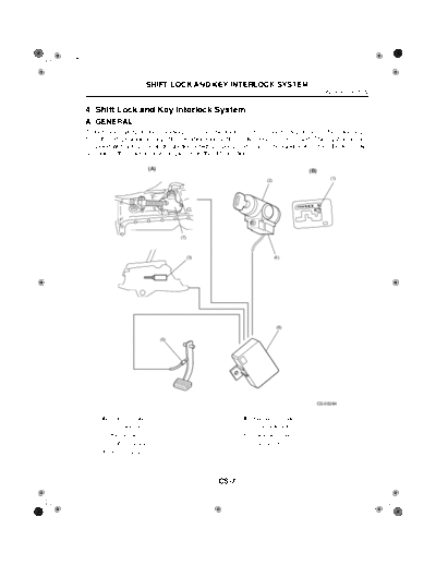
           To increase safety during standing start, the shift lock system prevents movement of the select lever
           from the "P" position to any other position unless the brake pedal is depressed. This system is also
           provided with a key interlock function which prevents removal of the ignition key from the key cylin-
           der unless the selector lever is placed in the "P" position.

                                              (A)                                                        (B)
                                                                                                                    (1)
                                                                                         (2)


                                                           (7)


                                                                 (3)                           (4)


                                                                                                (6)

                                                     (5)


                                                                                                               CS-00264


                    (A) Shift lock system                                     (B) Key interlock system
                    (1) "P" position switch                                   (5) Brake pedal switch
                    (2) Key cylinder                                          (6) Integrated module
                    (3) Shift lock solenoid                                   (7) Inhibitor switch
                    (4) Key lock solenoid


                                                                       CS-7
W1860BE.book Page 8 Tuesday, January 28, 2003 11:01 PM


                                   SHIFT LOCK AND KEY INTERLOCK SYSTEM
 CONTROL SYSTEM


 B: SHIFT LOCK SYSTEM OPERATION
 The shift lock system has a solenoid-operated plunger (1). With the select lever in the "P" position,
 the plunger remains extended, holding the lock arm (2) in its raised (locking) position. When the
 brake pedal is depressed with the ignition switch in either the ON or START position, the solenoid
 is energized and the plunger is retracted. This causes the lock arm to tilt forward to the select lever
 release position. The select lever now can be moved to any other position. The "P" position of the
 select lever is detected by the inhibitor switch (3).


                        (2)


                                                         (1)


                                                                                 (3)


                                                                                          CS-00161


                       (1) Solenoid
                       (2) Lock arm
                       (3) Inhibitor switch


                                                               CS-8
W1860BE.book Page 9 Tuesday, January 28, 2003 11:01 PM


                                              SHIFT LOCK AND KEY INTERLOCK SYSTEM
                                                                                                                      CONTROL SYSTEM


           C: KEY INTERLOCK FUNCTION
             When the select lever is at any position other than "P", the solenoid is energized and its pin is held
           extended. Being caused to stay in its upright position by extension of the pin, the interlock lever in-
           terferes with the stopper portion of the rotator which turns together with the ignition key. Thus, the
           ignition key cannot be rotated to the "LOCK" position.


                                                                                                                      (18)
                                                                       (1)


                                                                                                                      (19)
                                                                       (2)


                                                                       (3)

                                        (4)
                                 (5)
                                                                 (7)                                  (21)     (20)
                              (6)
                                                                (8)
                                                                              (11)
                                                                                      (12)
                                                          (9)           (9)
                                                                                                   (13)
                                                         (10)
                                                                                             (14)
                                                     A
                                                                                            (15)

                                                                              (17)   (16)
                                                            (18) (18)


                                                                                                                      CS-00078


                    (1) Column cover                                                    (12) Interlock position
                    (2) Key                                                             (13) Stopper
                    (3) Push button                                                     (14) ACC
                    (4) Extended                                                        (15) ON
                    (5) Solenoid pin                                                    (16) START
                    (6) Solenoid unit                                                   (17) View A
                    (7) Lever fulcrum                                                   (18) Rotator
                    (8) Lever spring                                                    (19) Key
                    (9) Interlock lever                                                 (20) Interlock lever
                  (10) Interlock activated                                              (21) Solenoid
                  (11) Lock


                                                                              CS-9
W1860BE.book Page 10 Tuesday, January 28, 2003 11:01 PM


                                   SHIFT LOCK AND KEY INTERLOCK SYSTEM
 CONTROL SYSTEM


    When the select lever is moved to "P", the "P" position switch in the select lever assembly oper-
 ates, deenergizing the solenoid. As the push force of the solenoid pin is removed, the lever spring
 causes the interlock lever to tilt and become clear of the rotator's stopper. Then the key can be ro-
 tated to the "LOCK" position and removed from the ignition switch.


                                                           (1)


                                                                      (2)


                                                                  CS-00079


                       (1) Retracted
                       (2) Interlock deactivated


                                                          CS-10
◦ Jabse Service Manual Search 2026 ◦ Jabse Pravopis ◦ onTap.bg ◦ Other service manual resources online : Fixya ◦ eServiceinfo