Service Manuals, User Guides, Schematic Diagrams or docs for : . Car Manuals Subaru Impreza 2001-2002.2004-2007 Approved Subaru Impreza 2004 WRX STi 08. MECHANISM AND FUNCTION 33. AUTOMATIC TRANSMISSION 08. Hydraulic Control Valve
<< Back | HomeMost service manuals and schematics are PDF files, so You will need Adobre Acrobat Reader to view : Acrobat Download Some of the files are DjVu format. Readers and resources available here : DjVu Resources
For the compressed files, most common are zip and rar. Please, extract files with Your favorite compression software ( WinZip, WinRAR ... ) before viewing. If a document has multiple parts, You should download all, before extracting.
Good luck. Repair on Your own risk. Make sure You know what You are doing.
Image preview - the first page of the document
>> Download 08. Hydraulic Control Valve documenatation <<
Text preview - extract from the document
W1860BE.book Page 14 Tuesday, January 28, 2003 11:01 PM
HYDRAULIC CONTROL VALVE
AUTOMATIC TRANSMISSION
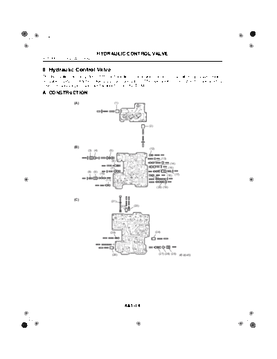
8. Hydraulic Control Valve
The hydraulic control system of the automatic transmission consists of an oil pump, valve bodies
containing valves, clutches, fluid passages and pipes. The operation of the system is initiated by
driver's manual inputs and electric inputs from the TCM.
A: CONSTRUCTION
(A) (1)
(2)
(B) (12)
(3) (4) (5)
(13)
(6)
(14)
(7) (15)
(8) (9)
(10)
(16) (17)
(18)
(11)
(20) (19)
(C) (21)
(22) (23)
(29) (24)
(28) (27) (26) (25) AT-00472
4AT-14
W1860BE.book Page 15 Tuesday, January 28, 2003 11:01 PM
HYDRAULIC CONTROL VALVE
AUTOMATIC TRANSMISSION
(1) High clutch accumulator piston B (12) Torque converter regulator valve (23) 1st reducing valve
(2) 2-4 brake accumulator piston B (13) Pressure modifier valve (24) Throttle accumulator piston A
(3) Pressure regulator sleeve (14) Accumulator control valve A (25) Lockup control sleeve
(4) Pressure regulator plug (15) Low clutch timing valve A (26) Lockup control plug
(5) Pressure regulator valve (16) Low clutch timing sleeve A (27) Lockup control valve
(6) Reverse inhibitor valve (17) Low clutch timing plug A (28) Modifier accumulator piston
(7) Accumulator control valve B (18) Low clutch timing valve B (29) Pilot valve
(8) 2-4 brake timing plug A (19) Shift valve B
(9) 2-4 brake timing sleeve A (20) Shift valve A (A) Upper valve body
(10) 2-4 brake timing valve A (21) Manual valve (B) Middle valve body
(11) 2-4 brake timing valve B (22) Throttle accumulator piston B (C) Lower valve body
4AT-15
W1860BE.book Page 16 Tuesday, January 28, 2003 11:01 PM
HYDRAULIC CONTROL VALVE
AUTOMATIC TRANSMISSION
B: FUNCTION
Name Function
Pressure regulator valve Regulates the pressure of ATF delivered from the oil pump to an optimum level (line
pressure) corresponding to vehicle running conditions.
Pressure modifier valve Adjusts the pressure modifier output pressure depending on the driving condition to
keep the line pressure at the optimum level.
Pressure modifier accumulator piston Cushions the pressure modifier valve output pressure to remove pulsation in line pres-
sure.
Line pressure relief valve Prevents excessive rise of the line pressure.
Manual valve Allows the line pressure to the circuit corresponding to the selected range.
Circuit (1) (2) (3) (4)
Range Line pressure
P PRND321 (4) (3)
R
N
D
3 (1) (2)
2
1
AT-00473
When the valve is placed in the position allowing the line pressure to go nowhere, the
pressure is released.
Pilot valve Reduces the line pressure to create a constant pressure (pilot pressure) for use in con-
trolling the line pressure, lockup pressure, and shifting and transfer clutch/brake pres-
sures.
Torque converter clutch regulator valve Prevents excessive rise of torque converter clutch pressure.
Lockup control valve Engages or disengages the lockup clutch.
Also regulates the lockup clutch engaging pressure to prevent lockup shocks.
Shift valve A Simultaneously changes three different ATF passages using shift solenoid 1 output
pressure which varies according to such operating condition factors as vehicle speed
and throttle position. In combination with shift valve B, this valve creates 1st, 2nd, 3rd,
and 4th speeds.
Shift valve B Simultaneously changes three different ATF passages using shift solenoid 2 output
pressure which varies according to such operating condition factors as vehicle speed
and throttle position. In combination with shift valve A, this valve creates 1st, 2nd, 3rd,
and 4th speeds.
Low clutch timing valve A Switches the ATF passages when the 2-4 brake pressure rises to a certain level during
3rd-to-4th upshifting in order to drain the low clutch accumulator back-pressure and to
release the low clutch. This ensures smoother shifting.
Low clutch timing valve B Returns the low clutch timing valve A to the original position after 3rd-to-4th upshifting.
2-4 brake timing valve A Switches the ATF passages when the high clutch pressure rises to a certain level dur-
ing 2nd-to-3rd upshifting in order to drain the 2-4 brake accumulator A back-pressure
and to release the 2-4 brake. This ensures smoother shifting.
2-4 brake timing valve B Returns the 2-4 brake timing valve A to the original position after 2nd-to-3rd upshifting.
Reverse inhibitor valve Allows the ATF in the low & reverse brake circuit to drain during forward driving at a
speed higher than the predetermined value, preventing shifting into the reverse even
when R range is selected.
1st reducing valve Reduces the low-reverse brake pressure so as to reduce engine braking shock when
changing from the 2nd to the 1st in the 2 range.
4AT-16
W1860BE.book Page 17 Tuesday, January 28, 2003 11:01 PM
HYDRAULIC CONTROL VALVE
AUTOMATIC TRANSMISSION
Name Function
Accumulator control valve A Regulates the accumulator control A pressure (low clutch accumulator A back-pres-
sure, high clutch accumulator A back-pressure, 2-4 brake timing control signal pres-
sure) depending upon driving conditions.
Accumulator control valve B Regulates the accumulator control B pressure (2-4 brake accumulator A back-pres-
sure, low clutch timing control signal pressure) depending upon driving conditions.
Low clutch accumulator Modulates the low clutch pressure gradually to damp shifting shocks when the low
clutch is engaged and disengaged.
2-4 brake accumulator A Modulates the 2-4 brake clutch pressure gradually to damp shifting shocks when the
2-4 brake clutch is engaged and disengaged.
2-4 brake accumulator B Slows down the 2-4 brake clutch pressure increase rate during 3rd-to-4th upshifting to
prevent timing variation which may occur when the low clutch timing valve A is switched
(to damp shifting shocks).
High clutch accumulator A Modulates the high clutch pressure gradually to damp shifting shocks when the high
clutch is engaged and disengaged.
High clutch accumulator B Slows down the high clutch pressure increase rate during 2nd-to-3rd upshifting to pre-
vent timing variation which may occur when the 2-4 brake clutch timing valve A is
switched (to damp shifting shocks).
Throttle accumulator A Cushions the output pressure of the line pressure duty solenoid valve to remove pul-
sation.
Throttle accumulator B Cushions the output pressure of the 2-4 brake duty solenoid valve to remove pulsation.
4AT-17
◦ Jabse Service Manual Search 2026 ◦ Jabse Pravopis ◦ onTap.bg ◦ Other service manual resources online : Fixya ◦ eServiceinfo